Elevator

A technology for elevators and elevators, applied in elevators, transportation and packaging, etc., can solve the problems of low passenger convenience and the inability of users to choose the destination floor on the spot

Active Publication Date: 2012-09-19
TOSHIBA ELEVATOR KK
View PDF5 Cites 7 Cited by
  • Summary
  • Abstract
  • Description
  • Claims
  • Application Information

AI Technical Summary

Problems solved by technology

[0004] However, in the safety system of the aforementioned elevator, information is input in advance before getting into the car, and the destinat

Method used


Image

  • Elevator
  • Elevator
  • Elevator

Examples


no. 1 Embodiment

[0023] First, the first embodiment will be described.

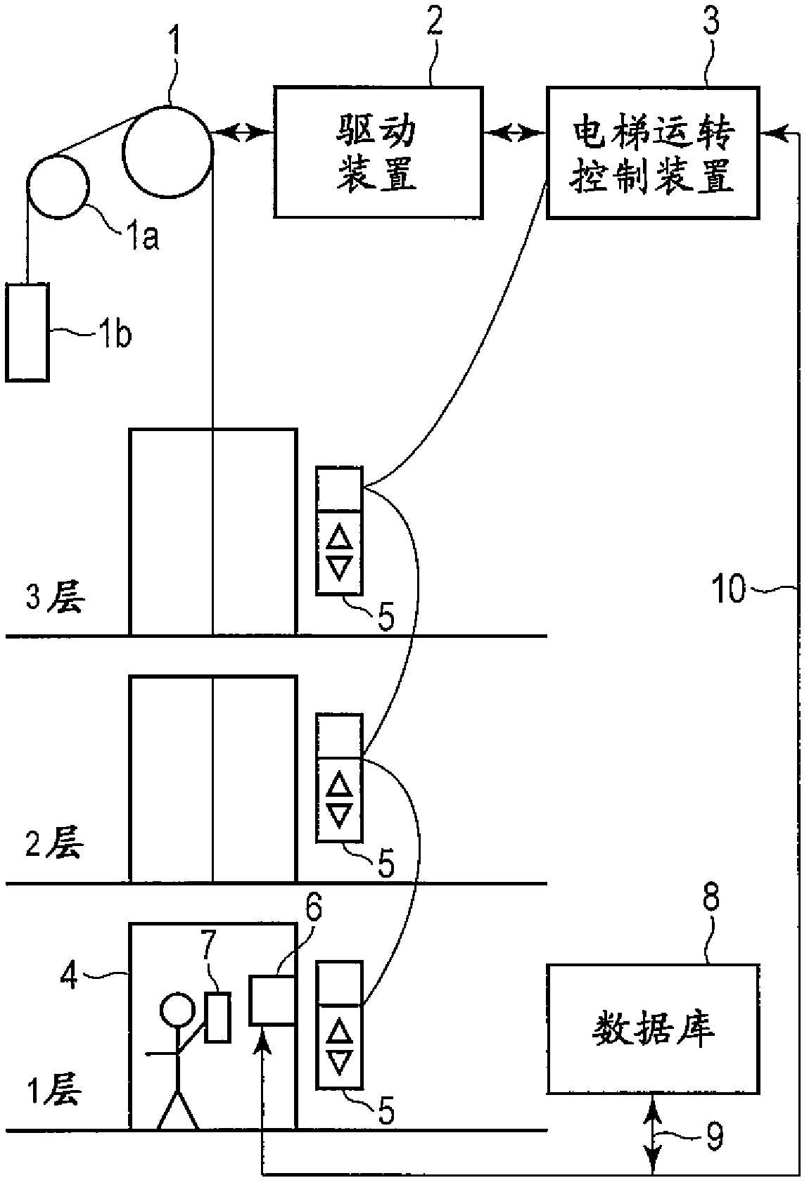
[0024] figure 1 It is a diagram showing a schematic configuration example of the elevator system in the first embodiment.

[0025] Such as figure 1 As shown, the elevator system in the first embodiment includes a sheave 1, a drive device 2, an elevator operation control device 3, a car 4, and a hall call registration device 5.

[0026] The car 4 is connected to a counterweight 1b via a main rope (main rope) wound around a pulley 1 and a deflection pulley 1a provided on a rotating shaft of a hoist (not shown). With the rotation of the pulley 1 driven by the hoisting machine, the car 4 is raised and lowered in vertically opposite directions together with the counterweight 1b in the hoistway by the frictional force between the pulley 1 and the main cable.

[0027] The driving device 2 rotates the pulley 1 by driving the hoist. The hall call registration device 5 is installed at the hall of each floor, and accepts a user'...

no. 2 Embodiment

[0055] Next, a second embodiment will be described. In addition, in the constitution of the elevator in each embodiment below and figure 1 The description of the same parts as shown is omitted.

[0056] Image 6 It is a diagram showing a schematic configuration example of the elevator system in the second embodiment.

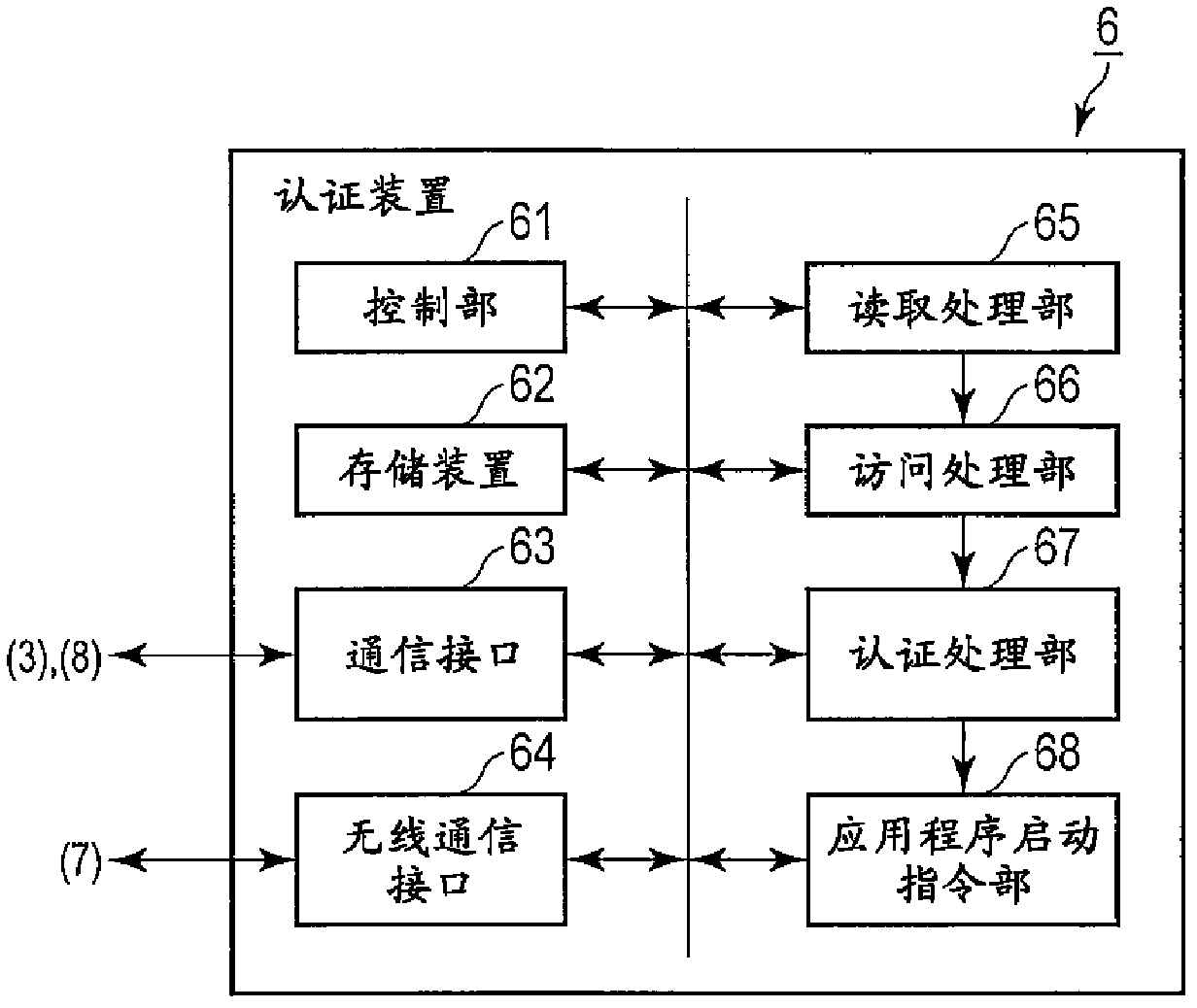
[0057] Such as Image 6 As shown, the elevator system in this embodiment is not provided with the landing call registration device 5 of the first embodiment, and the authentication device 6 described in the first embodiment is arranged at each landing of each floor outside the car 4 .

[0058] Figure 7 It is a flowchart of an example of the processing operation of the elevator system in the second embodiment.

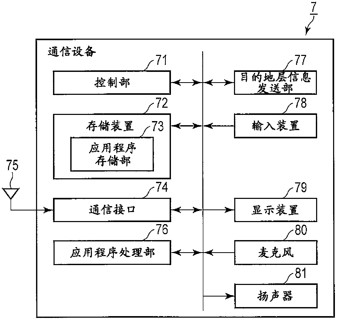
[0059] First, the elevator user brings the communication device 7 close to, for example, the authentication device 6 installed at the landing on the first floor, so that short-distance wireless communication between the wireless communication interf...

no. 3 Embodiment

[0070] Next, a third embodiment will be described. Figure 8 It is a diagram showing a schematic configuration example of the elevator system in the third embodiment.

[0071] Such as Figure 8 As shown, the elevator system in this embodiment is compared with the first embodiment, and an entrance lock device 11 is provided at the entrance of the first floor of the building. The entrance lock device 11 is communicably connected to the database 8 and the authentication device 6, and has a short-distance wireless communication function with the communication device 7 of the visitor, which is a user other than the resident of the building where the elevator is installed.

[0072] Figure 9 It is a block diagram showing an example of the functional configuration of the entrance lock device 11 of the elevator system in the third embodiment.

[0073] Such as Figure 9 As shown, the entrance lock device 11 of the elevator system in this embodiment has: a control unit 91 for contro...


PUM


Abstract

The present invention relates to an elevator having a function of performing personal identification for a user. The elevator can ensure safety performance in the premise of not reducing convenience of an elevator passenger. According to the embodiment, the elevator comprises: elevator taking position call register devices (5); a database (8) used for storing predetermined inherent user information of an elevator user; a reading processing part (65), which is arranged in an elevator car, and used for reading the inherent user information of the user stored in a communication device (7) held by the elevator user when the elevator taking position call is registered; an identification processing part (67) used for identifying the elevator user by checking the user information read by the reading processing part and the user information stored by the database; and an elevator operation control device (3) used for obtaining destination layer information input by an application program which is used for inputting of the destination layer information stored in the communication device held by the user when the identification processing part identifies the elevator user, performing destination layer register according to the obtained destination layer information, and performing operation control for the elevator car.

Description

[0001] This application is based on Japanese Patent Application No. 2011-057080 (filing date: March 15, 2011), and enjoys the priority of this application. This application incorporates the entire content of this application by reference. technical field [0002] An embodiment of the present invention relates to an elevator having a function of performing personal authentication of a user. Background technique [0003] Conventionally, as a technology related to the security system of an elevator, there is a method of making the car respond only to a specific floor for an authenticated user in conjunction with a door lock device installed at the entrance of a building. Entrance lock-linked elevator system and / or a system that pre-allocates cars to pre-designated floors by users pre-inputting information from their portable devices so that users can board smoothly. [0004] However, in the safety system of the aforementioned elevator, information is input in advance before bo...

Claims


Application Information

Patent Timeline
IPC IPC(8): B66B1/14B66B3/00
Inventor 衣笠满代
Owner TOSHIBA ELEVATOR KK
Why Eureka
Try Eureka