Hydraulically-driven roadblock machine

A roadblock machine and hydraulic technology, applied in the direction of roads, roads, traffic restrictions, etc., can solve the problems affecting the application of roadblock machines, the normal traffic of vehicles, and the large construction volume, and achieve the effect of compact structure, ingenious design and small construction volume.

Inactive Publication Date:
View PDF5 Cites 14 Cited by
  • Summary
  • Abstract
  • Description
  • Claims
  • Application Information

AI Technical Summary

Problems solved by technology

[0002] Due to structural design defects, the currently known hydraulic roadblocks are all giant-sized, and installation requires trenching on the road surface and burying the roadblocks underground as a whole, resulting in a very large amount of construction; in addition, already Due to the complex structure and large size of the known ground-mounted roadblocks, its overall height (height in the non-intercepting state) is difficult to achieve less than 90mm, so there are restrictions on the chassis of passing vehicles, which will not only affect The normal traffic of vehicles is affected, and it also affects the application of roadblock machines in many places

Method used


Image

  • Hydraulically-driven roadblock machine
  • Hydraulically-driven roadblock machine
  • Hydraulically-driven roadblock machine

Examples


Embodiment Construction

[0024] The present invention will be further described in detail below through embodiments in conjunction with the accompanying drawings.

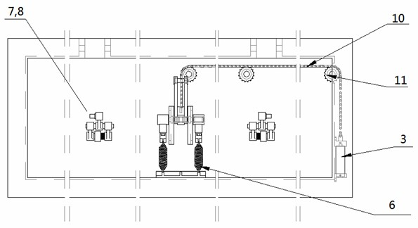
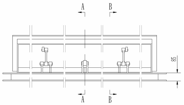
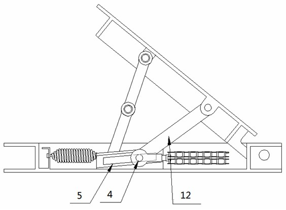
[0025] see Figure 1-Figure 6 , in one embodiment, the hydraulically driven roadblock machine includes a base 1, a cover plate 2 and a hydraulic driving device, the cover plate 2 is installed on the base 1, the hydraulic driving device is coupled to the cover plate 2, and the hydraulic driving device includes a hydraulic source, Transmission mechanism, roller 4, inclined block 5, cover plate strut 12 and elastic member, one end of cover plate 2 is hinged and fixed on machine base 1, hydraulic pressure source 3 is coupled to roller 4 through transmission mechanism, and roller 4 is arranged as It can be driven by the transmission mechanism to roll up on the inclined block 5 with an inclined surface. The driving direction is towards the side of the fixed end of the cover plate 2. The elastic member is set to transmit to the roller 4 so that i...


PUM


Abstract

The invention discloses a hydraulically-driven roadblock machine, which comprises a base, a cover plate and a hydraulic driving device. The cover plate is installed on the base. The hydraulic driving device is coupled on the cover plate and comprises a hydraulic source, a transmission mechanism, a rolling shaft, an inclined block, a cover plate supporting rod and an elastic piece. One end of the cover plate is fixedly hinged on the base. The hydraulic source is coupled to the rolling shaft through the transmission mechanism. The rolling shaft is arranged in a way that the rolling shaft can be driven by the transmission mechanism and can roll on the inclined block to move up, wherein the upwards moving direction faces towards one side of the fixed end of the cover plate. The elastic piece is arranged in a way that the elastic piece can transmit force to the rolling shaft to enable the rolling shaft to be restored downwards along the inclined block when the hydraulic source is turned off. The first end of the cover plate supporting rod is hinged on the rolling shaft. The second end of the cover plate supporting rod is hinged on the internal side of the cover plate. The hydraulically-driven roadblock machine provided by the invention ahs the advantages of compact and ingenious structure, small size, light weight, small thickness and wide application scope.

Description

technical field [0001] The invention relates to channel roadblock equipment, in particular to a hydraulically driven roadblock machine. Background technique [0002] Due to structural design defects, the currently known hydraulic roadblocks are all giant-sized, and installation requires trenching on the road surface and burying the roadblocks underground as a whole, resulting in a very large amount of construction; in addition, already Due to the complex structure and large size of the known ground-mounted roadblocks, its overall height (height in the non-intercepting state) is difficult to achieve less than 90mm, so there are restrictions on the chassis of passing vehicles, which will not only affect The normal traffic of vehicles is affected, and it also affects the application of roadblock machines in many places. Contents of the invention [0003] The main purpose of the present invention is to provide a hydraulic roadblock machine with a compact and ingenious structu...

Claims


Application Information

Patent Timeline
Patent Type & Authority Applications(China)
IPC IPC(8): E01F13/08
Inventor 唐健周自芳唐亮亮
Why Eureka
Try Eureka