Oil and gas separation device

A separation device, oil and gas separator technology, applied in the direction of engine components, machines/engines, mechanical equipment, etc., can solve problems such as separator failure, achieve the effect of balanced workload, consistent life, and avoid premature failure

Active Publication Date: 2014-05-28
WEICHAI POWER CO LTD
View PDF5 Cites 0 Cited by
  • Summary
  • Abstract
  • Description
  • Claims
  • Application Information

AI Technical Summary

Problems solved by technology

[0005] The technical problem to be solved by the present invention is to provide an oil-gas separation device. The structural design of the device can make the working load of each oil-gas separator balanced and the service life consistent, thereby avoiding the problem of premature failure of the separator with excessive work load

Method used


Image

  • Oil and gas separation device
  • Oil and gas separation device

Examples


Embodiment Construction

[0030] The core of the present invention is to provide an oil-gas separation device. The structural design of the device can make the working load of each oil-gas separator balanced and the service life consistent, thereby avoiding the problem of premature failure of the separator with excessive working load.

[0031] In order to enable those skilled in the art to better understand the technical solutions of the present invention, the present invention will be further described in detail below in conjunction with the accompanying drawings and specific embodiments.

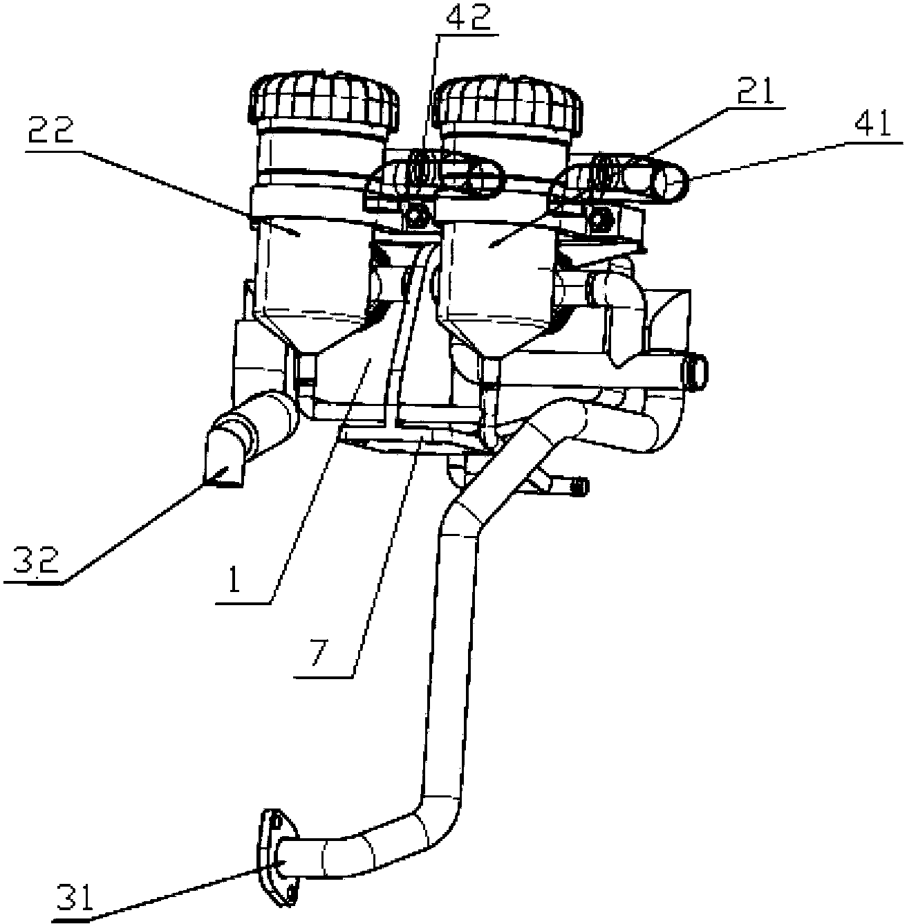
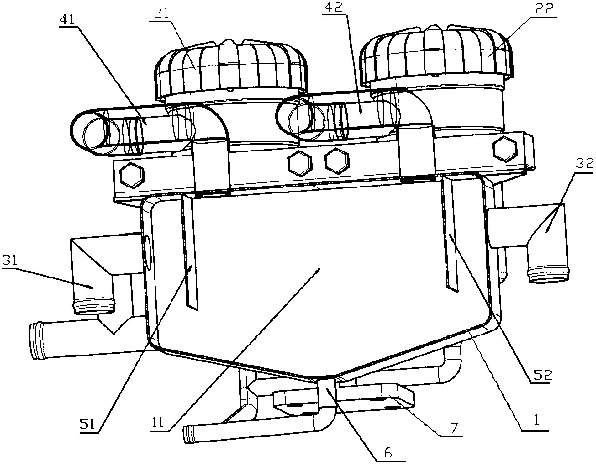
[0032] Please refer to figure 1 and figure 2 , figure 1 It is a structural schematic diagram of an oil-gas separation device in an embodiment of the present invention; figure 2 for figure 1 Rear view of the oil-gas separation unit in .

[0033] In one embodiment, the oil-gas separation device provided by the present invention is used to separate the oil-gas produced by internal combustion engines, such as fi...


PUM


Abstract

The invention discloses an oil and gas separation device, which is used for separating oil and gas generated by an internal combustion engine. The device comprises at lest two oil and gas separators, at least two gas sampling pipes for collecting the oil and the gas generated by the internal combustion engine, and an oil and gas mixer (1), wherein each gas sampling pipe is communicated with the oil and gas mixer (1), so that the collected oil and gas are input into the oil and gas mixer (1); and the oil and gas mixer (1) is communicated with the oil and gas separators through gas outlet pipes, so that the mixed oil and gas are input into the oil and gas separators. Due to the structural design of the device, the workload of each oil and gas separator is balanced, and the service life of each oil and gas separator is consistent, so that the problem that the separators are subjected to premature failure due to high workload is solved.

Description

technical field [0001] The invention relates to the technical field of internal combustion engines, in particular to an oil-gas separation device. Background technique [0002] During the working process of the internal combustion engine, the high-temperature and high-pressure gas in the combustion chamber will leak into the oil pan, causing the air pressure in the oil pan to be too high, which will form resistance to the reciprocating motion of the piston; in addition, the mixed gas discharged from the crankcase contains engine oil , In the process of recovery and combustion, it will be adsorbed on various parts of the internal combustion engine, forming carbon deposits, reducing the working performance of the internal combustion engine, accelerating the wear and tear of the internal combustion engine and waste of oil, reducing the working efficiency of the engine, shortening the service life, and emitting harmful gases to pollute the environment. Therefore, the internal co...

Claims


Application Information

Patent Timeline
Patent Type & Authority Patents(China)
IPC IPC(8): F01M13/04
Inventor 张英王军朱守江董晓婷
Owner WEICHAI POWER CO LTD
Why Eureka
Try Eureka