Energy-saving prying driving method for vehicle

A technology of vehicles and transmission wheels, which is applied in the direction of transmission devices, vehicle parts, portable lifting devices, etc.

Inactive Publication Date: 2012-09-19
陈翮
View PDF5 Cites 1 Cited by
  • Summary
  • Abstract
  • Description
  • Claims
  • Application Information

AI Technical Summary

Problems solved by technology

[0002] There has never been such a crowbar drive wheel and its matching veh

Method used


Image

  • Energy-saving prying driving method for vehicle
  • Energy-saving prying driving method for vehicle
  • Energy-saving prying driving method for vehicle

Examples


Embodiment Construction

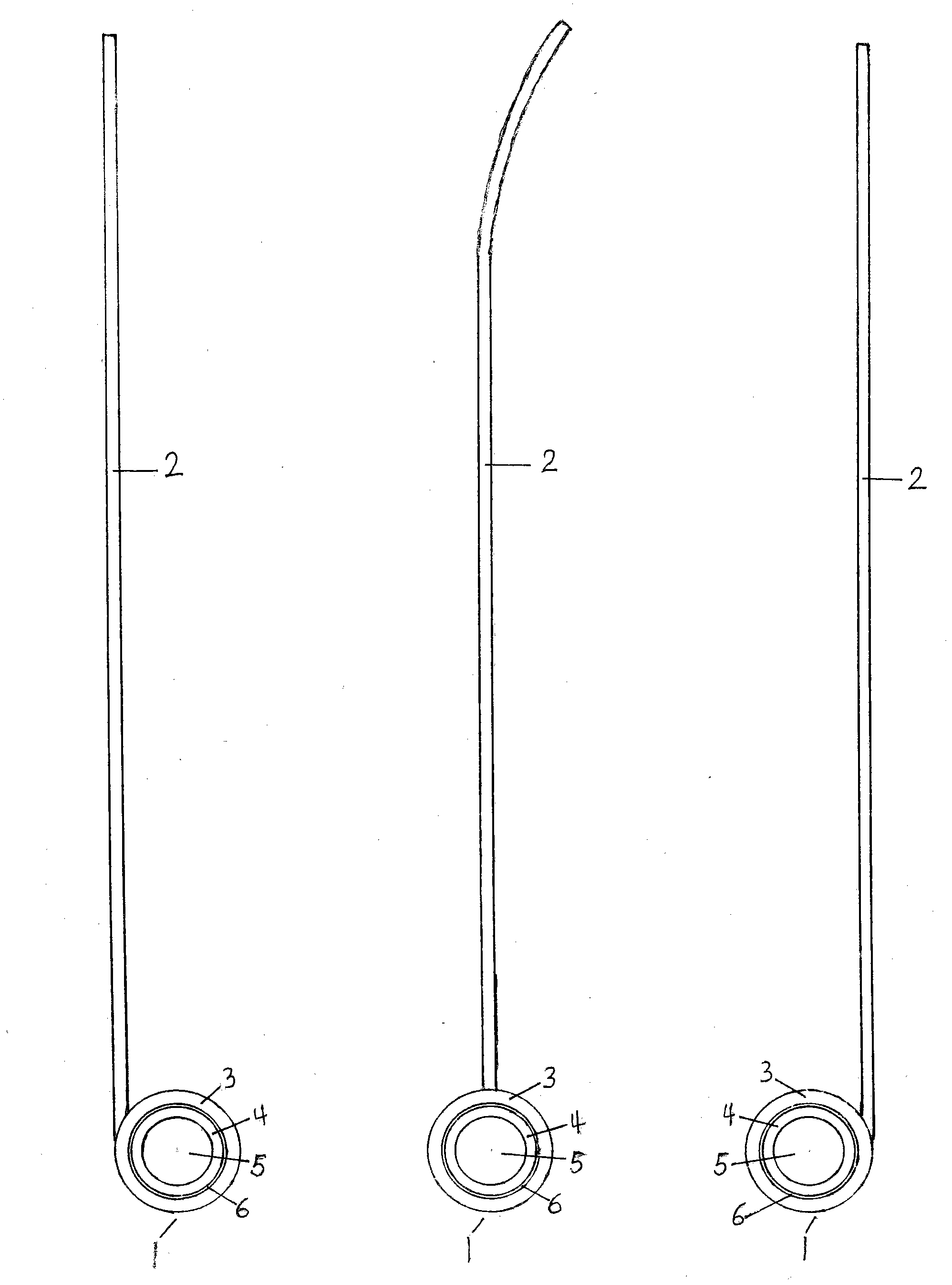
[0043] figure 1 is a schematic diagram of the pry bar drive wheel. In the figure, the internal structures of the three transmission wheels are the same, but the positions of the crowbars are different. 1 in the figure is the drive wheel; 2 is the pry bar fixed on the outer ring of the drive wheel; 3 is the outer ring of the drive wheel; 4 is the inner ring of the drive wheel; 5 is the inner hole of the drive wheel, which is set behind the vehicle Play fixed effect on the transverse axis; 6 is the joint mouth of outer ring and inner ring, and two circles of balls are housed in the inside, also have steel teeth and oblique notch, and the internal structure of bicycle flywheel is basically identical (made in the content of the invention the inside for details). Pull up the pry bar of the drive wheel of the pry bar, the steel teeth inside the drive wheel can be locked, and the pry bar can be pressed down to pry.

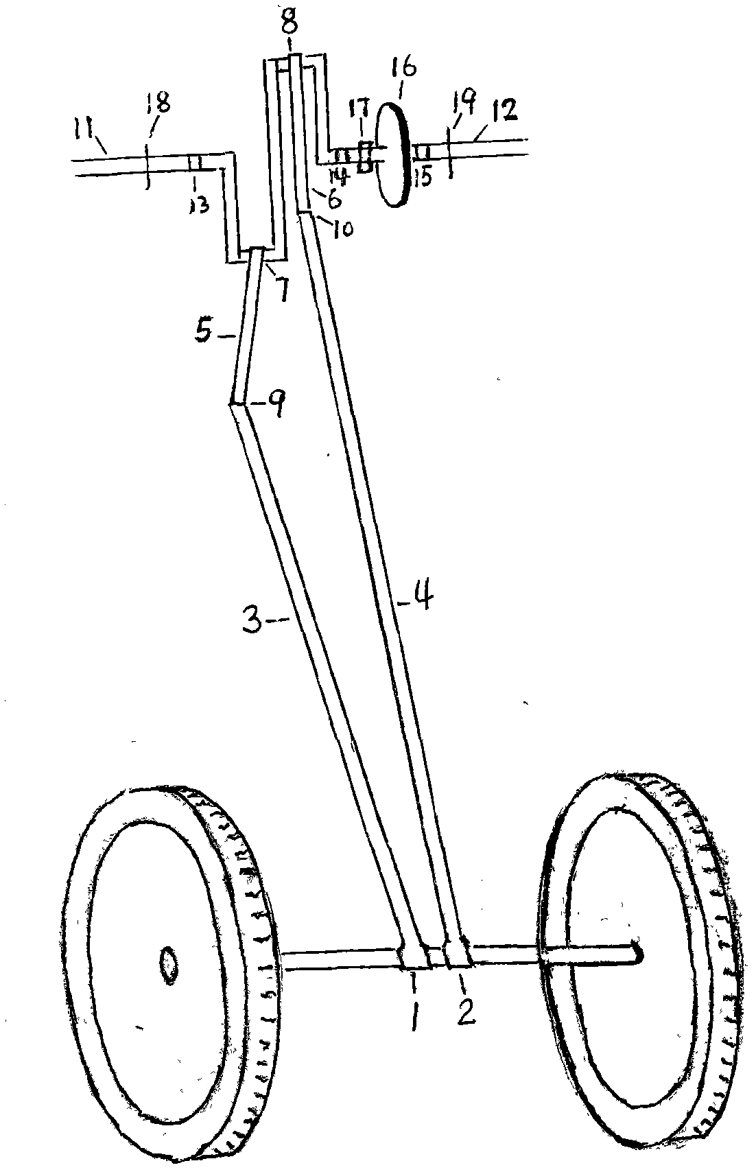
[0044] figure 2 It is a schematic diagram of a crowbar drive w...


PUM


Abstract

The invention discloses prying bar driving wheels for driving a vehicle, two vehicle driving devices matched with the prying bar driving wheels and a driving method. Two to a plurality of prying bar driving wheels are arranged in the middle of a rear transverse shaft of the vehicle and are used for prying the rear transverse shaft of the vehicle and enabling rear wheels to rotate forwards. The vehicle driving devices matched with the prying bar driving wheels are generally arranged at the rear of a vehicle head or at the front, in the middle or on the lower part of a vehicle body, two to a plurality of connecting rods are movably connected to the vehicle driving devices, the other end of each connecting rod is movably connected with a prying bar head of the corresponding prying bar driving wheel, and when the vehicle driving devices are driven electrically or driven by a fuel machine, the connecting rods are pulled to vertically move and then pull prying bars of the prying bar driving wheels to perform sequential relay-type prying. Continuous high-frequency alternative prying of the prying bars drives the vehicle to run forwards. The prying bars of the prying bar driving wheels are long or ultra-long, and therefore, the prying bars and the matched vehicle driving devices can drive the vehicle in a labor-saving manner. A vehicle comprising the prying bar driving wheels and the matched vehicle driving devices is energy-saving and environment-friendly.

Description

technical field [0001] The invention relates to a crowbar drive wheel for vehicle transmission and two vehicle transmission devices and transmission methods matching it. Background technique [0002] There is no such crowbar transmission wheel and its matching vehicle transmission and vehicle in the Internet search and the market. Contents of the invention [0003] The first technical problem to be solved by the present invention is to provide a crowbar drive wheel for vehicle transmission. The crowbar on this drive wheel is longer or extra long, and the length of the crowbar is determined by the size and concrete application of the vehicle. [0004] The crowbar driving wheel must be driven by other vehicle transmissions to play its role. [0005] The crowbar transmission wheel is generally installed in the middle part of the rear transverse axis of automobiles, tricycles, or other vehicles. According to the needs of transmission, two or more can be installed, and other ...

Claims


Application Information

Patent Timeline
IPC IPC(8): F16H51/00F16H21/12F16H37/12F16H55/17B60K17/00
Inventor 陈翮
Owner 陈翮
Why Eureka
Try Eureka