Hydraulic control butterfly valve

A technology of hydraulic control butterfly valve and valve body, which is applied in the direction of lift valve, valve details, valve device, etc., can solve the problems of butterfly plate valve and bearing bush corrosion, reducing the service life of hydraulic control butterfly valve, and poor sealing effect of hydraulic control butterfly valve, etc. Achieve the effect of avoiding rust and improving service life

Inactive Publication Date: 2012-09-19
SUZHOU GUANGFU METALLURGY CASTING
View PDF0 Cites 4 Cited by
  • Summary
  • Abstract
  • Description
  • Claims
  • Application Information

AI Technical Summary

Problems solved by technology

The sealing effect of such a hydraulically controlled butterfly valve is not good, which will easily lead to corrosion of the butterfly plate valve and bearing bush, and reduce the service life of the hydraulically controlled butterfly valve

Method used


Image

  • Hydraulic control butterfly valve
  • Hydraulic control butterfly valve
  • Hydraulic control butterfly valve

Examples


Embodiment Construction

[0013] The present invention is described below in conjunction with accompanying drawing.

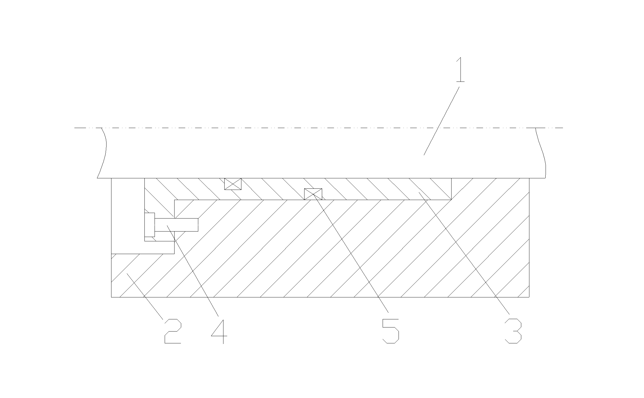
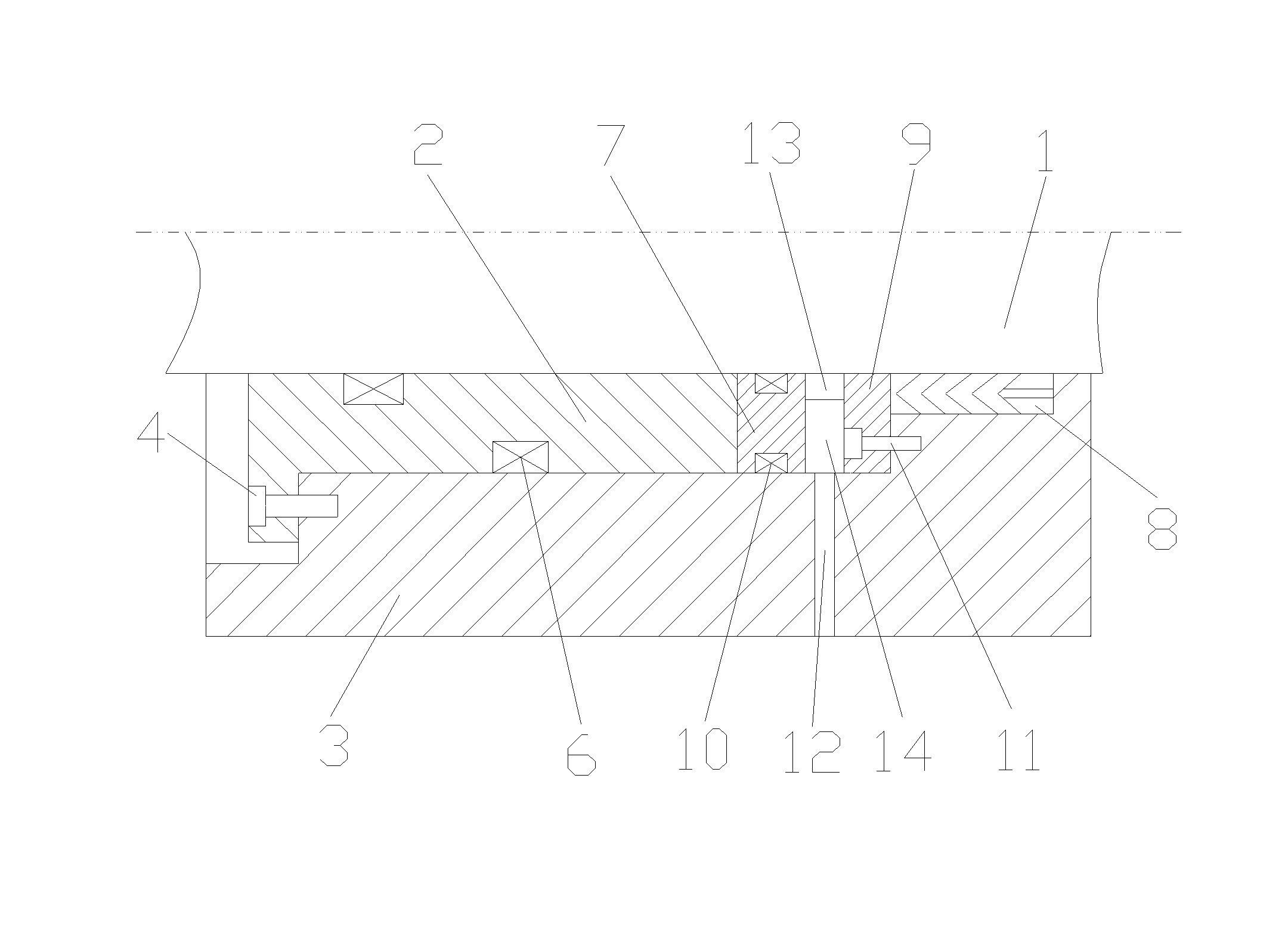
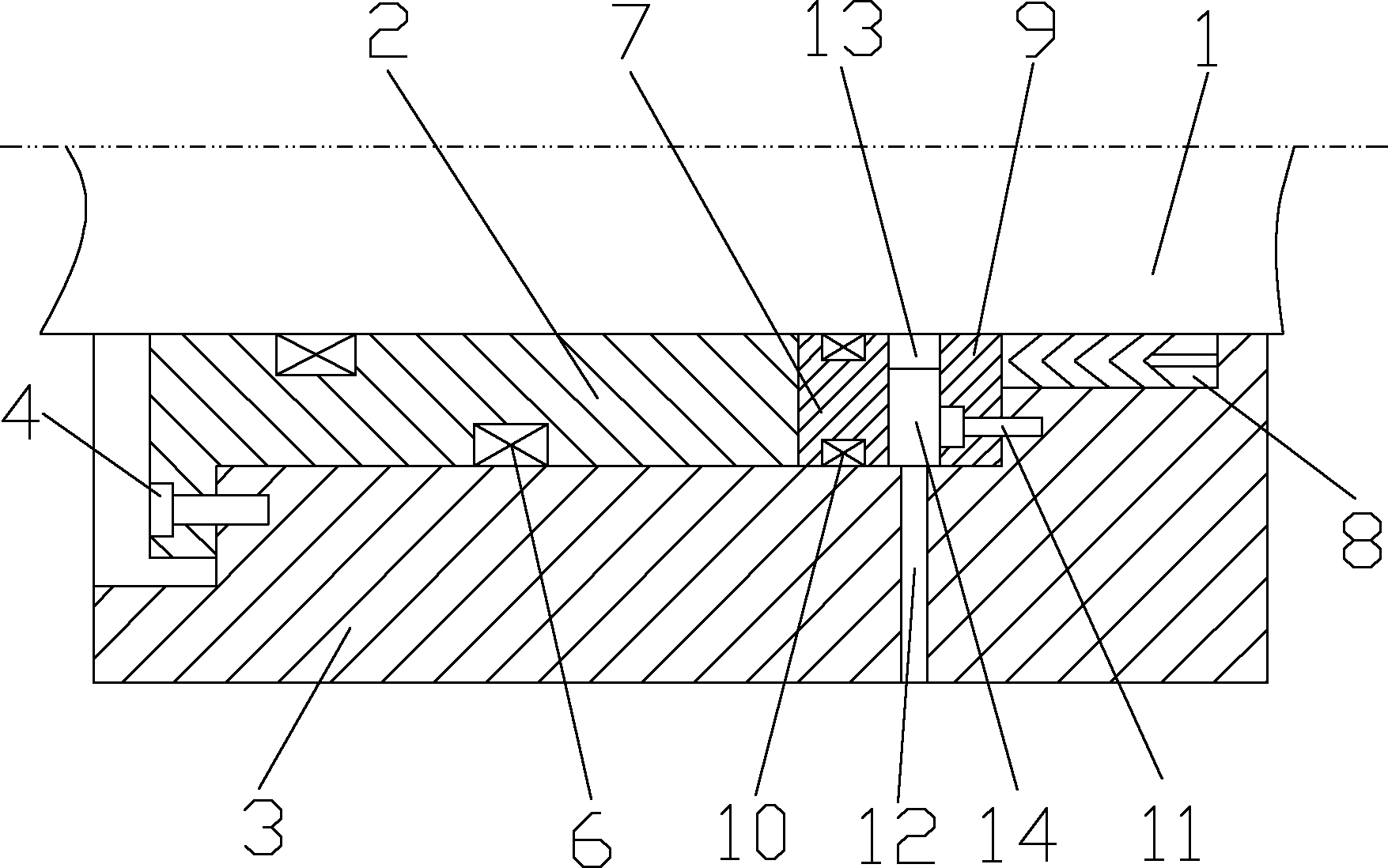
[0014] as attached figure 2 The hydraulic control butterfly valve shown in the present invention includes a butterfly plate shaft 1, a bearing bush 2, a valve body 3, an inner hexagon screw 4 and a first O-shaped sealing ring 6, and the valve body 3 is provided with a butterfly plate Shaft 1, the valve body 3 and the butterfly plate shaft 1 are provided with a bearing bush 2, the bearing bush 2 is connected with the valve body 3 through the hexagon socket head screw 4, the contact part of the bearing bush 2 and the butterfly plate shaft 1 and the valve body 3 There is a first O-shaped sealing ring 6, and a sealing device is provided between the head of the bearing bush 2 and the valve body 3 and the butterfly plate shaft 1; the sealing device includes a sealing spacer 7, a V-shaped fabric sealing ring 8 and Gland 9; the sealing spacer 7 is in close contact with the head of the bearing...


PUM


Abstract

The invention discloses a hydraulic control butterfly valve which comprises a butterfly plate shaft, a bearing bush, a valve body, an inner hexagon screw and a first O-shaped sealing ring. The butterfly plate shaft is arranged in the valve body, the bearing bush is arranged between the valve body and the butterfly plate shaft and is connected with the valve body through the inner hexagon screw, the first O-shaped sealing ring is arranged at the contact portion of the bearing bush, the butterfly plate shaft and the valve body, and a sealing device is arranged among the head portion of the bearing bush, the valve body and the butterfly plate shaft; the sealing device comprises a sealing isolation pad, a V-shaped clamping fabric sealing ring and a gland; the sealing isolation pad abuts against the head of the bearing bush; second O-shaped sealing rings are arranged among the contact portions of the sealing isolation pad respectively, the butterfly plate shaft and the valve body respectively; the V-shaped clamping fabric sealing ring is arranged on the other side of the sealing isolation pad; and the V-shaped clamping fabric sealing ring is fixed between the valve body and the butterfly plate shaft through the gland. The hydraulic control butterfly valve has the advantages that the sealing effect is good, the butterfly plate shaft and the bearing bush are effectively prevented from being rusted, and the service life is improved.

Description

technical field [0001] The invention relates to a hydraulically controlled butterfly valve, in particular to a hydraulically controlled butterfly valve with good sealing performance. Background technique [0002] The hydraulic control butterfly valve is a regulating valve with a simple structure. It is generally used in similar places such as the pump outlet pipeline of the pump station. It can control or cut off the pipeline medium in two directions, avoiding and reducing the backflow of the medium in the pipeline system and the large water generated by the pipeline. hammer effect. The hydraulic control butterfly valve in the prior art, as attached figure 1 As shown, it includes butterfly plate shaft 1, bearing bush 2, valve body 3, hexagon socket head screw 4 and O-ring 5, the valve body 3 is provided with butterfly plate shaft 1, and the valve body 3 and butterfly plate shaft are provided with bearing bush 2 , The bearing bush 2 is connected with the valve body 3 throu...

Claims


Application Information

Patent Timeline
Patent Type & Authority Applications(China)
IPC IPC(8): F16K1/22F16K41/06
Inventor 府爱明
Owner SUZHOU GUANGFU METALLURGY CASTING
Why Eureka
Try Eureka