

Tensile flexible pipe
A hose and tension technology, applied in the direction of hoses, hose connection devices, pipes, etc., can solve the problems of harsh supply operation environment, hose performance and service life discount, mutual dragging of supply ships and receiving ships, etc., to achieve Save time for replenishment work, improve cargo transfer capacity, and avoid ship collision accidents
- Summary
- Abstract
- Description
- Claims
- Application Information
AI Technical Summary
Problems solved by technology
Method used
Image

Examples
Embodiment Construction
[0037] Specific embodiments of the present invention will be described below with reference to the accompanying drawings.
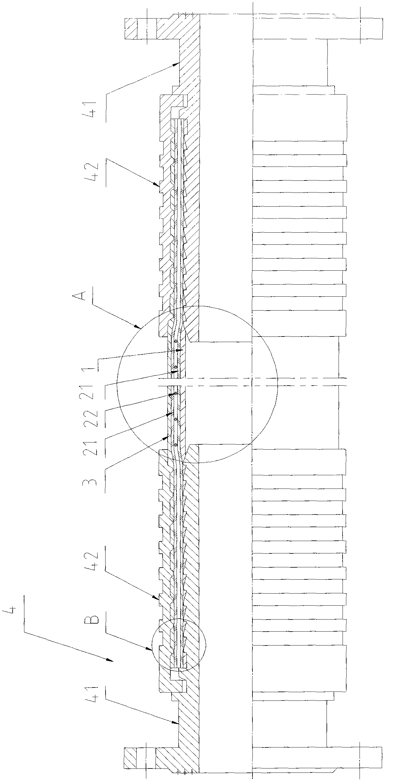
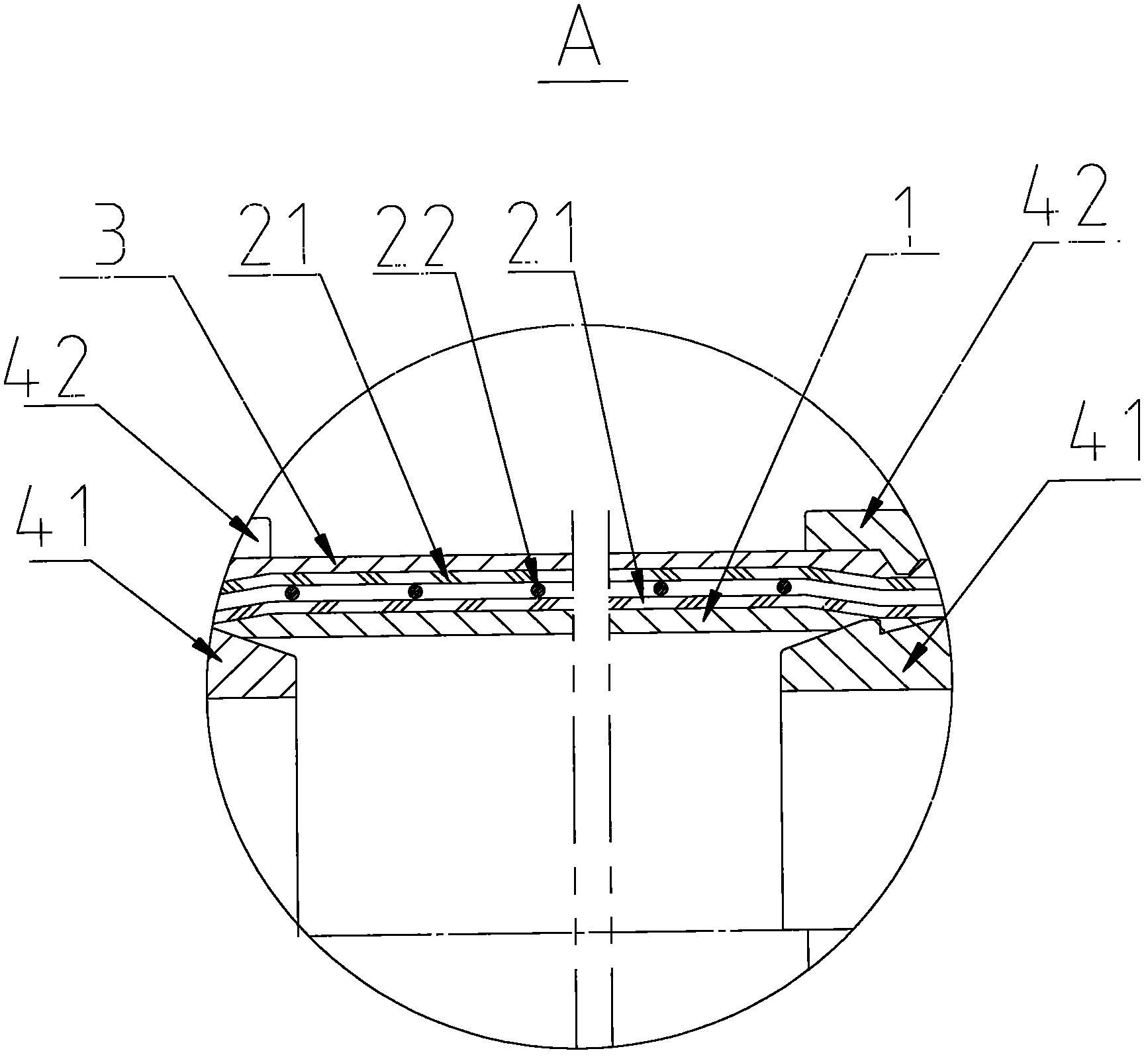
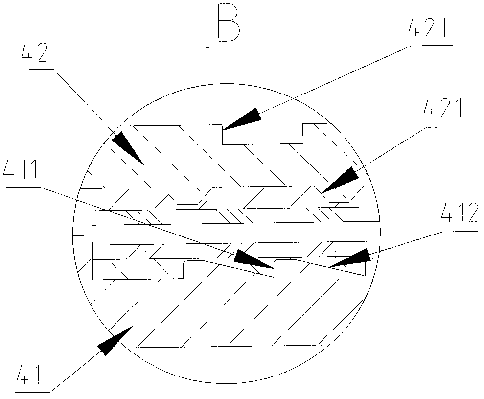
[0038] figure 1 It is a structural schematic diagram of an embodiment of the tension hose according to the present invention; figure 2 yes figure 1 The enlarged schematic diagram of part A shown; image 3 yes figure 1 An enlarged schematic view of part B is shown.
[0039] Such as Figure 1 to Figure 3 As shown, the present invention provides a tension hose, which sequentially includes an inner rubber layer 1, a skeleton layer and an outer rubber layer 3 from inside to outside, and is characterized in that the skeleton layer includes a fiber layer 21 and is sandwiched between the fiber layers The metal spiral layer 22 in the middle of 21, the inner rubber layer 1 is used to transport the liquid medium, and has resistance and tightness to the transported liquid medium; the skeleton layer 2 is the supporting structure of the tension hose , to withsta...
PUM
| Property | Measurement | Unit |
|---|---|---|
| Pull | aaaaa | aaaaa |
Abstract
Description
Claims
Application Information