Automatic welding method and controller

An automatic welding and automatic technology, applied in welding equipment, welding equipment, auxiliary welding equipment, etc., can solve the problems of difficult to achieve automatic welding, low welding efficiency, long process time, etc. Welding speed, the effect of reducing the amount of welding wire

Active Publication Date: 2022-04-15
ZOOMLION HEAVY IND CO LTD
View PDF8 Cites 2 Cited by
  • Summary
  • Abstract
  • Description
  • Claims
  • Application Information

AI Technical Summary

Problems solved by technology

[0002] The welding technology in the prior art has the following disadvantages, especially for the welding of long cylindrical workpieces with a length of more than 9 meters or a plate with a wall thickness of less than 10 mm: the butt weld of long and thin-walled members cannot be completely melted in one weld. penetration, it is difficult to realize automatic welding, there are many processes that require manual participation, the quality of the weld is difficult to guarantee, and it is easy to produce welding defects without penetration, the back is difficult to penetrate, and the quality of the back of the weld is unstable and inefficient in manual rooting welding. Problems such as low efficiency of ordinary MAG welding have become the bottleneck of boom capacity improvement. The existing boom is manually grounded and then automatically welded to cover the surface. The process takes a long time and the welding filling is large, which easily leads to welding deformation. Most of the deformation is more than 5mm, and it is a typical wave-like instability deformation. It is difficult to correct after welding. Driving takes a lot of time, affects the efficiency of the entire production line, and takes up a lot of space, the amount of welding wire is large, and there is a lot of spatter after welding

Method used


Image

  • Automatic welding method and controller
  • Automatic welding method and controller
  • Automatic welding method and controller

Examples


Embodiment Construction

[0023] The specific implementation manners of the embodiments of the present invention will be described in detail below in conjunction with the accompanying drawings. It should be understood that the specific implementation manners described here are only used to illustrate and explain the embodiments of the present invention, and are not intended to limit the embodiments of the present invention.

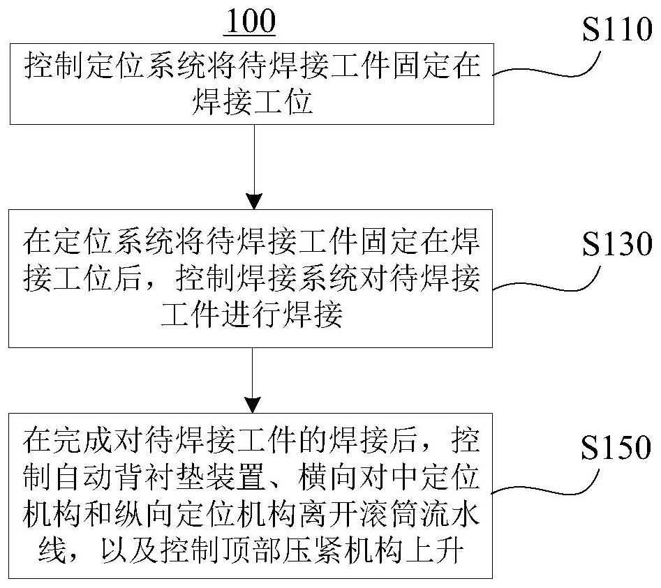
[0024] Such as figure 1 As shown, in the embodiment of the present invention, an automatic welding method 100 is provided, which is applied to a welding workstation. Among them, the welding workstation includes: positioning system and welding system. The automated welding method 100 includes the following steps:

[0025] Step S110: Control the positioning system to fix the workpiece to be welded at the welding station. as well as

[0026] Step S130: After the positioning system fixes the workpiece to be welded at the welding station, control the welding system to weld the work...


PUM


Abstract

The embodiment of the invention provides an automatic welding method and a controller, the automatic welding method is applied to a welding workstation, and the welding workstation comprises a positioning system and a welding system; the automatic welding method comprises the steps that the positioning system is controlled to fix a workpiece to be welded to a welding station; and after the positioning system fixes the to-be-welded workpiece to the welding station, the welding system is controlled to weld the to-be-welded workpiece. According to the embodiment of the invention, automatic control and one-time welding complete penetration in the welding process can be realized, welding deformation is reduced, the welding speed is increased, the welding wire consumption is reduced, two procedures of groove milling and backing welding are canceled, equipment, personnel and sites are reduced, and the production efficiency is improved. The time of two working procedures of groove milling and backing welding and the time for transferring and waiting for traveling caused by the two working procedures are saved, welding spatter is little, and only one person is needed for guarding.

Description

technical field [0001] The invention relates to the field of welding technology, in particular to an automatic welding method and a controller. Background technique [0002] The welding technology in the prior art has the following disadvantages, especially for the welding of long cylindrical workpieces with a length of more than 9 meters or a plate with a wall thickness of less than 10 mm: the butt weld of long and thin-walled members cannot be completely melted in one weld. penetration, it is difficult to achieve automatic welding, there are many processes that require manual participation, the quality of the weld is difficult to guarantee, and it is easy to produce welding defects without penetration, the back is difficult to penetrate, and the quality of the back of the weld is unstable and inefficient in manual rooting welding. Problems such as low efficiency of ordinary MAG welding have become the bottleneck for raising the capacity of the boom. The existing boom is ma...

Claims


Application Information

Patent Timeline
Patent Type & Authority Applications(China)
IPC IPC(8): B23K28/02B23K37/04B23K37/00
Inventor 王莲芳刘松良刘玮陈铁坚艾卫中谢湘华
Owner ZOOMLION HEAVY IND CO LTD
Why Eureka
Try Eureka