
Precision test device and method of electric energy quality monitor

A technology of power quality monitoring and inspection methods, applied in the direction of measuring devices, measuring electrical variables, instruments, etc., can solve problems such as low efficiency and prone to human errors, and achieve the effect of improving work efficiency

Active Publication Date: 2012-09-19
STATE GRID JIANGSU ELECTRIC POWER CO ELECTRIC POWER RES INST +1
View PDF7 Cites 6 Cited by
  • Summary
  • Abstract
  • Description
  • Claims
  • Application Information

AI Technical Summary

Problems solved by technology

[0002] The current power quality monitor accuracy inspection device is to connect the standard source with a number of inspected equipment (that is, the power quality monitor), manually read the display data of the standard source and the displayed data of the inspected equipment, and manually list and record them. After calculation and summary, the final To form an accuracy test report, since most of the power quality data are statistical data, and the readings from the standard source and the tested equipment are all instantaneous data, it is necessary to record several sets of instantaneous data for statistical calculation, which is inefficient and prone to man-made mistake

Method used


Image

  • Precision test device and method of electric energy quality monitor
  • Precision test device and method of electric energy quality monitor
  • Precision test device and method of electric energy quality monitor

Examples


Embodiment Construction

[0023] Below in conjunction with accompanying drawing and specific embodiment, further illustrate the present invention, should be understood that these embodiments are only for illustrating the present invention and are not intended to limit the scope of the present invention, after having read the present invention, those skilled in the art will understand various aspects of the present invention Modifications in equivalent forms all fall within the scope defined by the appended claims of this application.

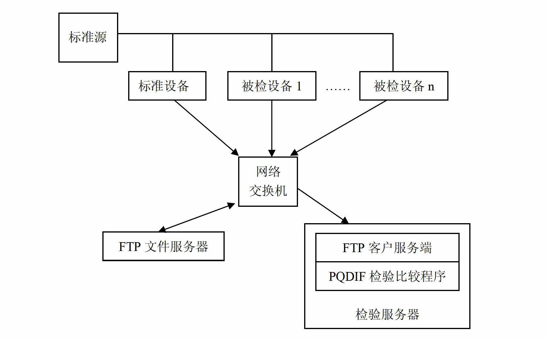
[0024] Such as figure 1 As shown, the standard source, standard equipment, several tested equipment, network switch, FTP file server and testing server constitute the accuracy testing device of the power quality monitor.

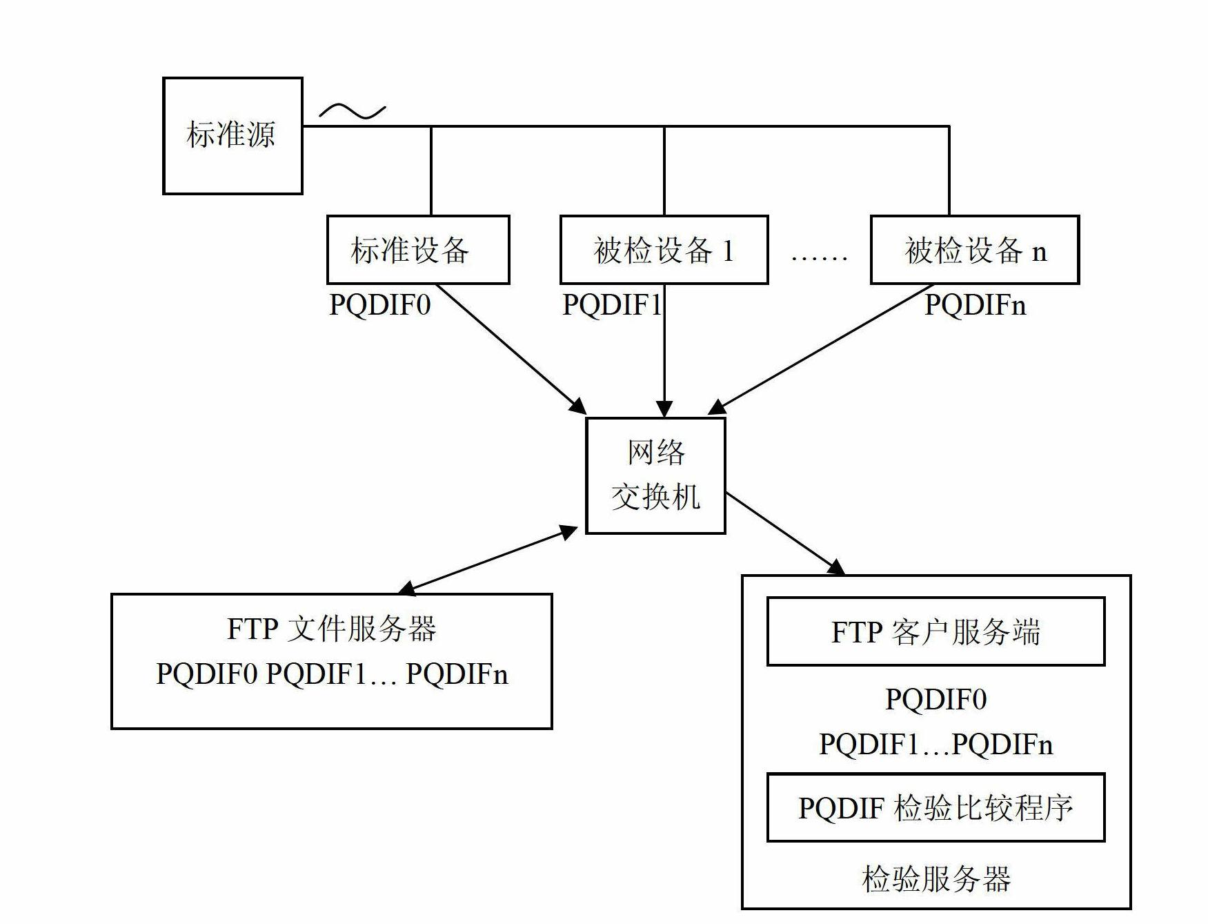
[0025] Such as figure 2 As shown, the standard source generates power signals, and the standard equipment, tested equipment 1, ..., and tested equipment n simultaneously collect the power signals generated by the standard source to form power quality...


PUM


Abstract

The invention discloses a precision test device of an electric energy quality monitor. The precision test device comprises a standard source, standard equipment, a detected equipment, a network switchboard, a first server and a second server, wherein the standard equipment and the detected equipment are respectively connected with the standard source; the standard equipment, the detected equipment, the first server and the second server are connected through the network switchboard to form a local area network; and the standard source is used for generating a signal to be detected, the standard equipment and the detected equipment are used for respectively acquiring the signal to be detected to respectively generate data packets and upload the respective data packet onto the first server through the network switchboard, and the second server is used for reading the data packet of the first server through the network switchboard and comparing the data packet from the standard equipmentwith the data packet from the detected equipment. The invention further discloses a precision test method of the electric energy quality monitor. According to the precision test device and method disclosed by the invention, the working efficiency can be improved and artificial errors are thoroughly eliminated.

Description

technical field [0001] The invention relates to the technical field of electric energy quality detection, in particular to a precision inspection device and inspection method for an electric energy quality monitor. Background technique [0002] The current power quality monitor accuracy inspection device is to connect the standard source with a number of inspected equipment (that is, the power quality monitor), manually read the display data of the standard source and the displayed data of the inspected equipment, and manually list and record them. After calculation and summary, the final To form an accuracy test report, since most of the power quality data are statistical data, and the readings from the standard source and the tested equipment are all instantaneous data, it is necessary to record several sets of instantaneous data for statistical calculation, which is inefficient and prone to man-made mistake. Contents of the invention [0003] Purpose of the invention: ...

Claims


Application Information

Patent Timeline
Patent Type & Authority Applications(China)
IPC IPC(8): G01R35/00
Inventor 陈兵
Owner STATE GRID JIANGSU ELECTRIC POWER CO ELECTRIC POWER RES INST
Learn More