Liquid display panel, liquid crystal display and 3D (three-dimensional) imaging system

A liquid crystal display panel, liquid crystal display technology, applied in the directions of instruments, optics, nonlinear optics, etc., can solve problems such as image crosstalk, and achieve the effect of avoiding image crosstalk

Active Publication Date: 2012-09-19
TCL CHINA STAR OPTOELECTRONICS TECH CO LTD
View PDF3 Cites 15 Cited by
  • Summary
  • Abstract
  • Description
  • Claims
  • Application Information

AI Technical Summary

Problems solved by technology

[0004] An object of the present invention is to provide a liquid crystal display panel to sol

Method used


Image

  • Liquid display panel, liquid crystal display and 3D (three-dimensional) imaging system
  • Liquid display panel, liquid crystal display and 3D (three-dimensional) imaging system
  • Liquid display panel, liquid crystal display and 3D (three-dimensional) imaging system

Examples


Example Embodiment

[0044] The following descriptions of the various embodiments refer to the accompanying drawings to illustrate specific embodiments in which the invention may be practiced. The directional terms mentioned in the present invention, such as "up", "down", "front", "rear", "left", "right", "inside", "outside", "side", etc., are only for reference Additional schema orientation. Therefore, the directional terms used are for describing and understanding the present invention, not for limiting the present invention. In the figures, structurally similar elements are denoted by the same reference numerals.

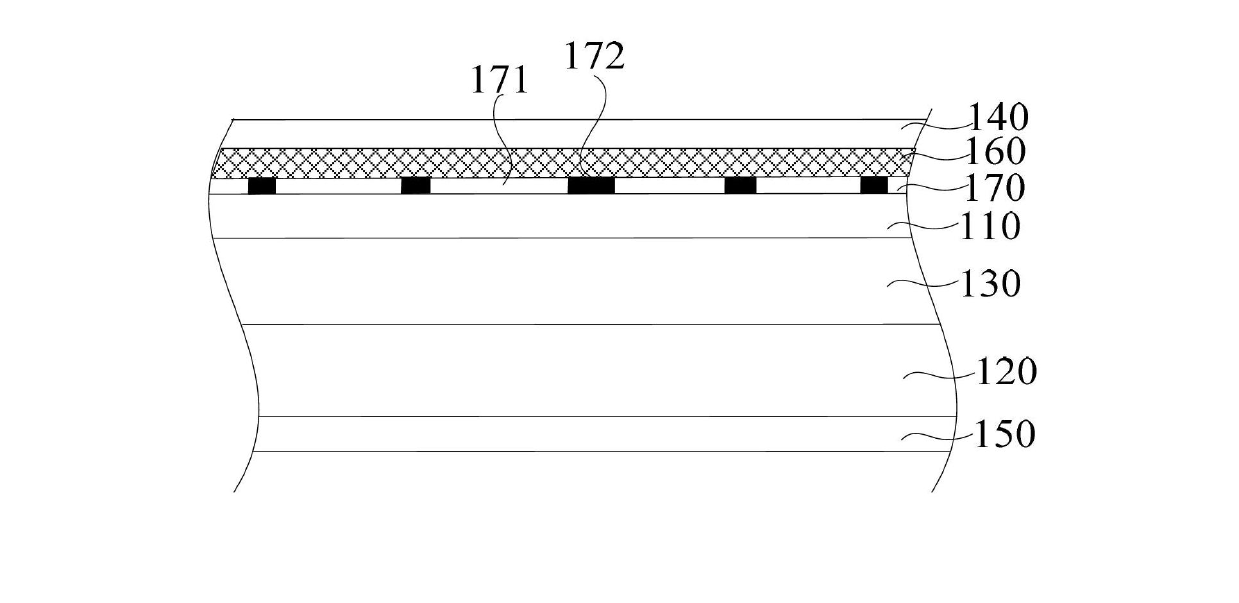
[0045] figure 2 It is a schematic cross-sectional structure diagram of the first preferred embodiment of the liquid crystal display panel of the present invention.

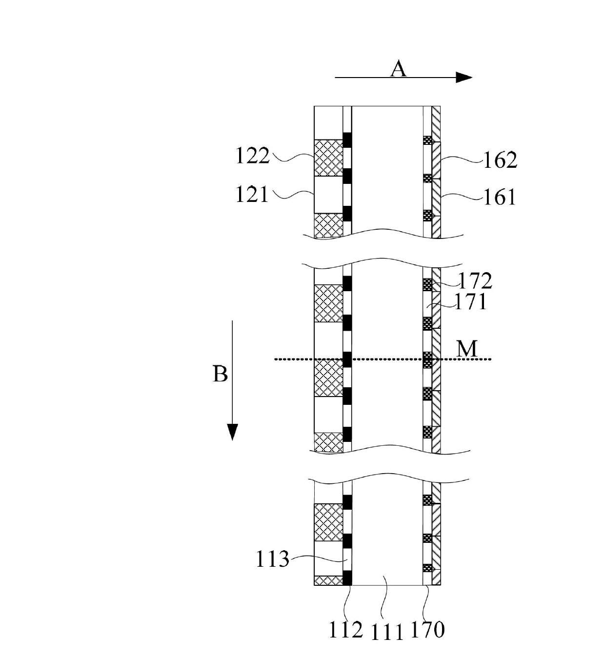
[0046] Please refer to figure 2 , which shows a partial cross-sectional schematic diagram of a liquid crystal display panel according to an embodiment of the present invention. The liquid crystal display of this e...


PUM


Abstract

The invention provides a liquid display panel, a liquid crystal display and a 3D (three-dimensional) imaging system. The liquid display panel comprises a first substrate, a second substrate, a liquid crystal layer, a phase delay sheet and an anti-dazzling sheet; the phase delay sheet comprises a first phase delay sheet and a second phase delay sheet; the anti-dazzling sheet is arranged at the outer side of the first substrate, and corresponds to a black matrix of the first substrate; the anti-dazzling sheet comprises a plurality of light transmitting units and a plurality of anti-dazzling units, which are configured in a staggered manner; and the anti-dazzling units are respectively located between the first phase delay sheet and the second phase delay sheet. According to the liquid display panel provided by the invention, the anti-dazzling sheet is arranged at the outer side of the first substrate, so that the anti-dazzling sheet can shield light of a bias adhered area when the first phase delay sheet or the second phase delay sheet is subjected to bias adhesion offset. Therefore, the image crosstalk can be avoided.

Description

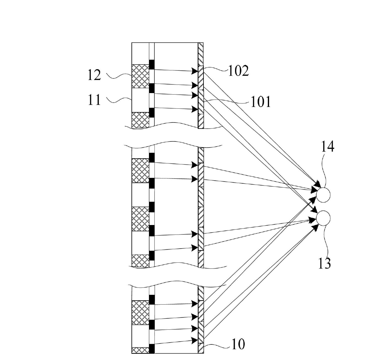
【Technical field】 [0001] The present invention relates to the technical field of liquid crystal display, and in particular, to a liquid crystal display panel, a liquid crystal display and a 3D image system. 【Background technique】 [0002] see figure 1 , the pixel area of ​​the 3D liquid crystal display includes a left eye pixel area 11 and a right eye pixel area 12, the phase retardation plate 10 is attached to the outside of the 3D liquid crystal display, and the phase retardation plate 10 includes a left eye phase retardation plate 101 and a right eye phase retardation plate 101 The slice 102 corresponds to the left-eye pixel area 11 and the right-eye pixel area 12 respectively. When attaching the phase retardation film 10, the attaching machine generally has an attaching error of about 20um. When an attachment error occurs, for example, the right-eye phase retarder 102 approaches the left-eye phase retarder 101 by 20um, the right-eye phase retarder 102 will direct the l...

Claims


Application Information

Patent Timeline
IPC IPC(8): G02F1/1333G02F1/1335G02B27/22
CPCG02F1/1335G02B27/22G02F1/133512G02F1/133631
Inventor 萧嘉强陈峙彣
Owner TCL CHINA STAR OPTOELECTRONICS TECH CO LTD
Why Eureka
Try Eureka