Redundant circuit and redundancy conversion method
A redundant circuit and resistor technology, applied in the direction of electrical program control, comprehensive factory control, etc., can solve the problems of affecting the work of the working module, poor contact of the spare module, misjudging that there is no working module, etc.
- Summary
- Abstract
- Description
- Claims
- Application Information
AI Technical Summary
Problems solved by technology
Method used
Image

Examples
Embodiment 1
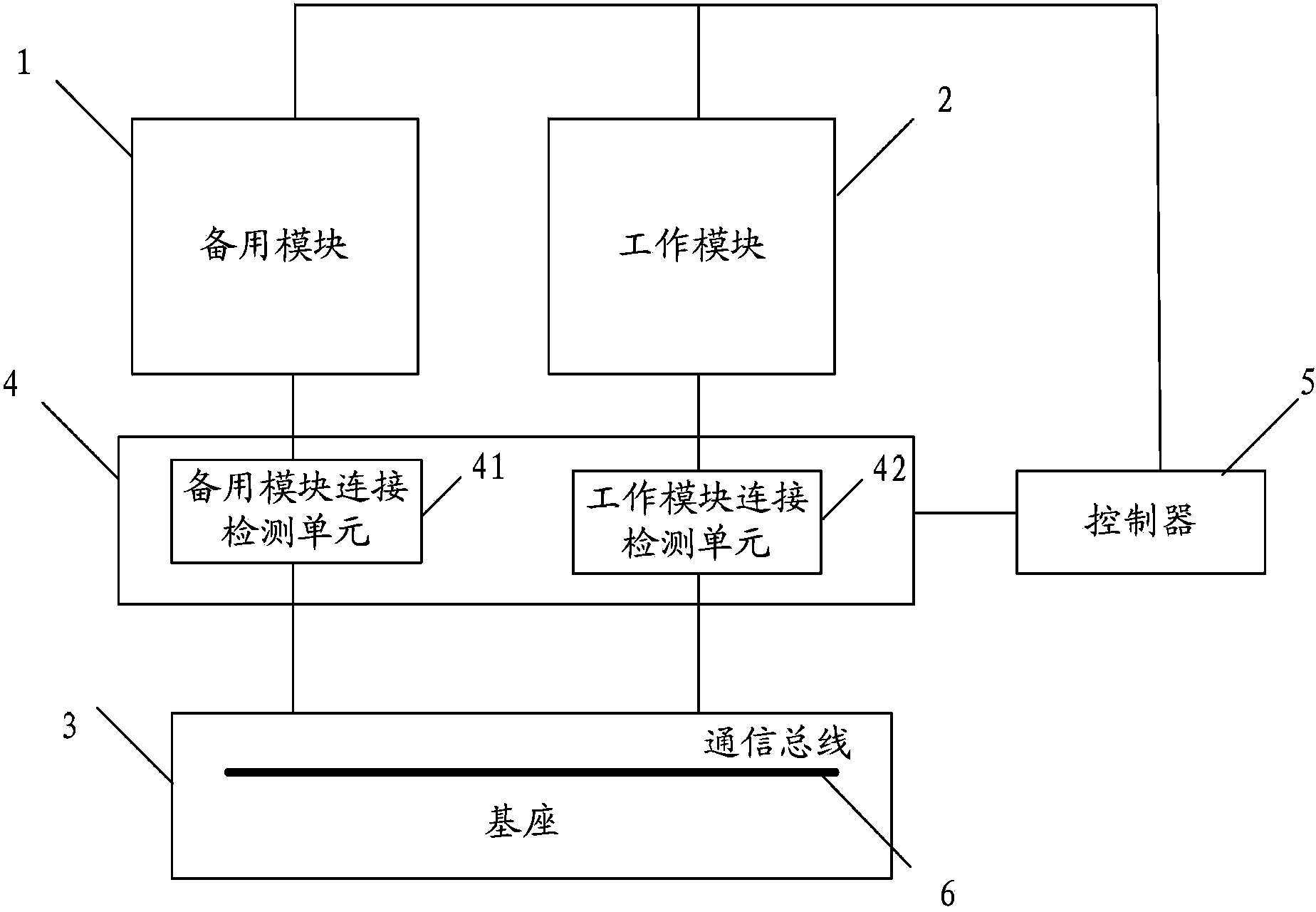
[0063] figure 1 The structure block diagram of the redundant circuit provided for the implementation of this application.
[0064] Such as figure 1 As shown, the redundant circuit includes: a spare module 1, a working module 2, a base 3, a redundant diagnostic circuit 4, and a controller 5. Among them:
[0065] Both the standby module 1 and the working module 2 are connected to the base 3 through a hot plug interface (not shown in the figure), and a redundant communication interface is provided between the standby module 1 and the working module 2, which is set in the base There is a communication bus 6. Under normal conditions, if the working module 1 is working, then the working module 1 will interact with the communication bus 6.
[0066] Such as figure 1 As shown, the redundant diagnostic circuit 4 includes a standby module connection detection unit 41 and a working module connection detection unit 42, and the standby module connection detection unit 41 is connected in series bet...
Embodiment 2
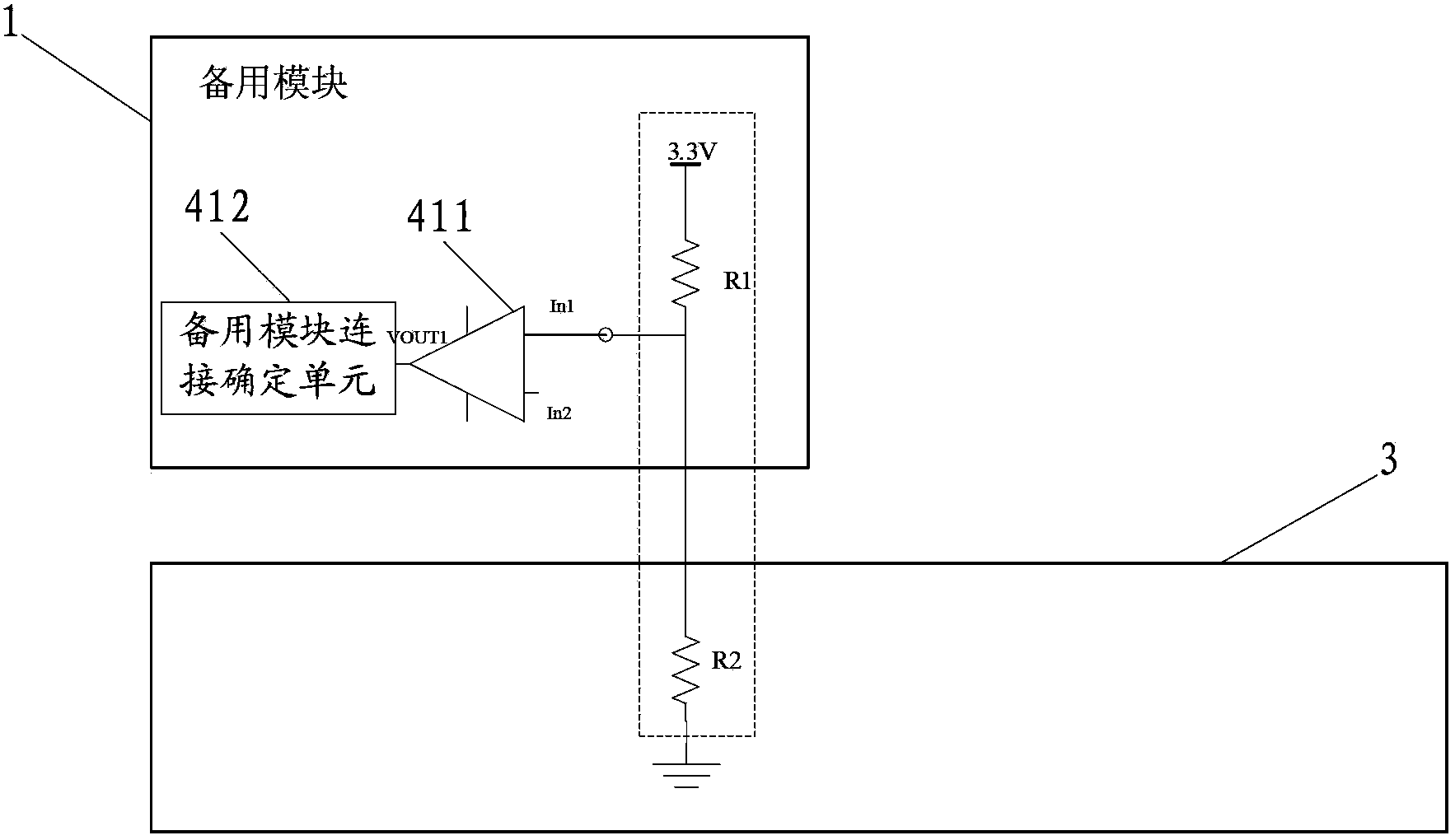
[0072] figure 2 This is a schematic diagram of a circuit structure of a redundant circuit provided in an embodiment of this application.
[0073] Such as figure 2 As shown, in the embodiment of the present application, the standby module detection unit 41 includes: a first resistor R1, a second resistor R2, a first comparison unit 411, and a standby module connection determination unit 412, wherein:
[0074] The first resistor R1 may be arranged in the standby module 1, and one end of the first resistor R1 is connected to the reference voltage in the standby module 1, and the other end is connected to one end of the second resistor R2 through a hot plug interface. The second resistor R2 may be arranged in the base 3, and the other end of the second resistor R2 is connected to the ground level in the base 3.
[0075] In the above circuit structure, the first resistor R1 is connected in series with the second resistor R2 through the hot plug interface, so by detecting the voltage at ...
Embodiment 3
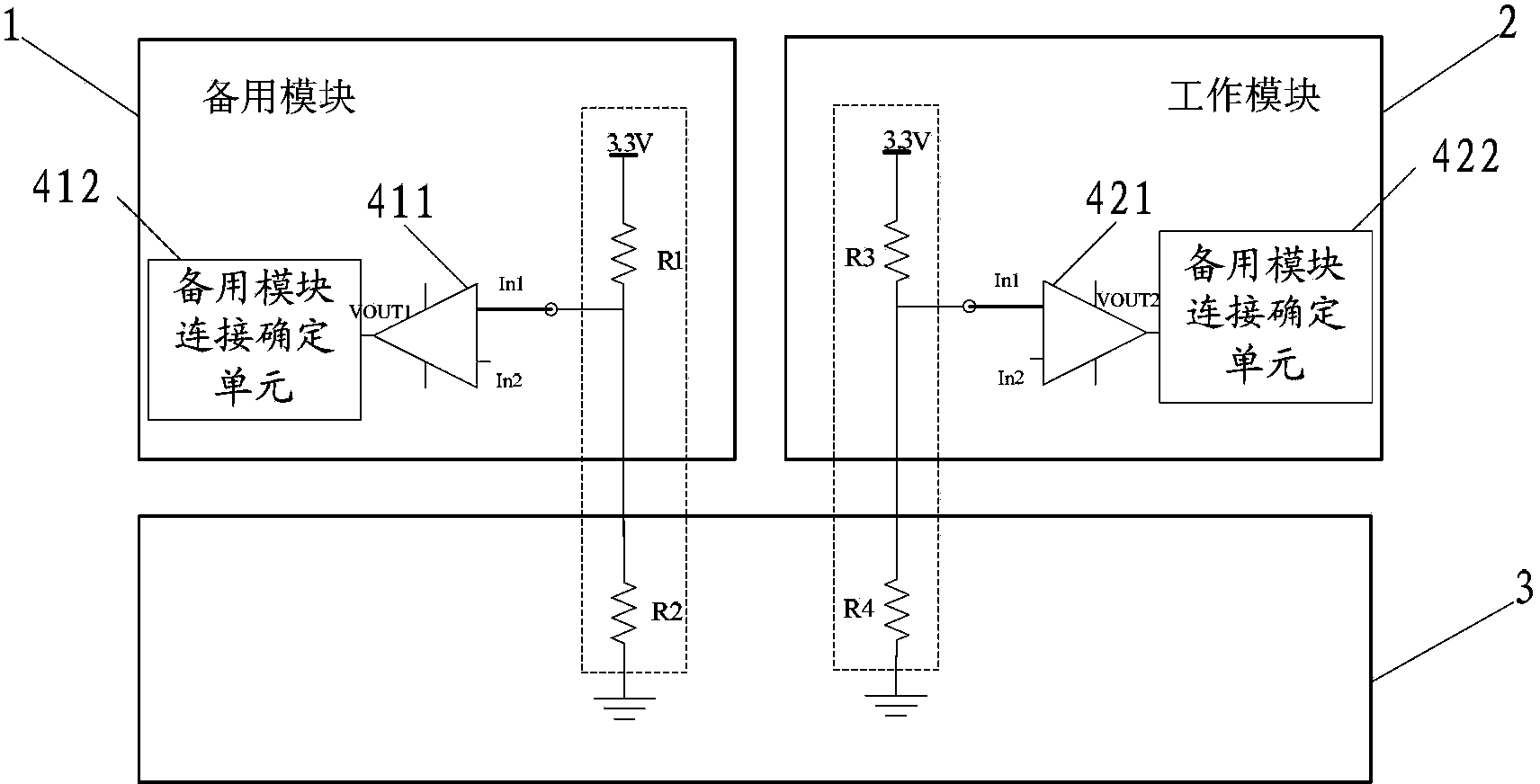
[0083] image 3 This is a schematic diagram of another circuit structure of the redundant circuit provided in the embodiment of this application.
[0084] Such as image 3 As shown, based on the second embodiment, the working module detection unit 42 in the redundant circuit may include: a third resistor R3, a fourth resistor R4, a second comparison unit 421, and a working module connection determination unit 422, where :
[0085] The third resistor R3 may be arranged in the working module 2, and one end of the third resistor R3 is connected to the reference voltage in the working module 2, and the other end is connected to one end of the fourth resistor R4 through a hot plug interface, and the fourth resistor R4 It can be set in the base, and its other end is connected to the ground level in the base 3.
[0086] Here, the third resistor R3 is connected in series with the fourth resistor R4 through the hot-swappable interface, so by detecting the voltage at the end connecting the fi...
PUM
 Abstract
Description
Claims
Application Information
 - R&D
- Intellectual Property
- Life Sciences
- Materials
- Tech Scout
- Unparalleled Data Quality
- Higher Quality Content
- 60% Fewer Hallucinations
Browse by: Latest US Patents, China's latest patents, Technical Efficacy Thesaurus, Application Domain, Technology Topic, Popular Technical Reports.
© 2025 PatSnap. All rights reserved.Legal|Privacy policy|Modern Slavery Act Transparency Statement|Sitemap|About US| Contact US: help@patsnap.com