Multifunctional watchdog circuit

A watchdog and multi-functional technology, applied in the field of watchdog circuits, can solve problems such as inability to self-diagnose, watchdog circuits cannot handle complex faults, etc., and achieve the effect of improving safety

Active Publication Date: 2012-09-19
CHINA TECHENERGY +1
View PDF4 Cites 20 Cited by
  • Summary
  • Abstract
  • Description
  • Claims
  • Application Information

AI Technical Summary

Problems solved by technology

[0006] In order to solve the problem that the watchdog circuit in the prior art cannot handle complex faults and cannot self-diagnose itself, the present invention provides a watchdog circuit that judges the cause of the fault by detecting the number of resets and gives an alarm in time. At the same time, the watchdog circuit With self-diagnosis function, the specific scheme is as follows: a multi-functional watchdog circuit, including a microprocessor module that provides a dog feed signal for the watchdog module, a watchdog module that outputs a reset signal when the program is abnormal, and a sending microprocessor The reset signal of the device module and the reset module A and reset module B that send counting signals to the counter module, and the counting module that counts the number of resets, wherein the output of the microprocessor module is connected to the input of the watchdog module and the counting module respectively Connection, the output of the watchdog module is connected to the input of the reset module A, the output of the reset module A is connected to the input of the microprocessor module and the counting module, and the output of the counting module is connected to the microprocessor through the reset module B. The device module is connected, and it is characterized in that, the output end of reset module A is connected with the total counting module that records the reset total number of times in unit time, and the output end of total counting module is connected with reset module B

Method used


Image

  • Multifunctional watchdog circuit
  • Multifunctional watchdog circuit
  • Multifunctional watchdog circuit

Examples


Embodiment Construction

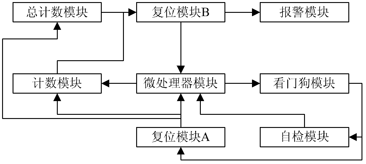
[0015] Such as figure 1 As shown, the multifunctional watchdog circuit of this program includes a control center and an MCU (microprocessor module) that provides a dog feed signal for the watchdog module, and an automatic timing watchdog module that outputs a reset signal when the program is abnormal. The reset module A and reset module B that forward the reset signal to the MCU and send the count signal to the counting module, and the counting module that records the number of resets, the connection relationship between the above modules is: the output terminal of the MCU and the watchdog module The input terminal is connected to input the WDI signal (feeding dog signal), connected to the input terminal of the counter module to reset the counter, the output terminal of the watchdog module is connected to the input terminal of the reset module A to input the reset signal for MCU reset, and the reset module The output terminals of A are respectively connected to the input termi...


PUM


Abstract

The invention relates to a multifunctional watchdog circuit which comprises a microprocessor module, a watchdog module, a reset module A, a reset module B and a counting module. An output end of the microprocessor is respectively connected with input ends of the watchdog module and the counting module, an output end of the watchdog module is connected with an input end of the reset module A, an output end of the reset module A is respectively connected with input ends of the microprocessor module and the counting module, an output end of the counting module is connected with the microprocessor module via the reset module B, the output end of the reset module A is connected with a total counting module which records a total number of the reset in a unit time, and an output end of the total counting module is connected with the reset module B. Since detection of multiple functions is realized in the watchdog circuit, bad consequences caused by program faults, MCU (micro-programmed control unit) faults, periodic faults and watchdog chip faults are effectively controlled and reduced, and safety of the watchdog circuit is improved.

Description

technical field [0001] The invention relates to a watchdog circuit, in particular to a watchdog circuit capable of judging the severity of a fault and having a self-checking function. Background technique [0002] Various software programs will have code errors, and designers must ensure that the system does not appear deadlock. In addition, noise and EMI will also affect the data in the system, resulting in unpredictable system actions. The basic function of the watchdog circuit is to reset the system to the normal working state after a software problem occurs or the program runs away, including a counter. When the system is stuck somewhere or runs away, the timer in the watchdog When the counter overflows, a reset signal is output to the microprocessor, and the counter counts automatically at the same time, and the counter is reset and cleared after the microprocessor is reset. A watchdog circuit is a simple, inexpensive solution to increasing system reliability. [0003...

Claims


Application Information

Patent Timeline
Patent Type & Authority Applications(China)
IPC IPC(8): G06F11/07
Inventor 陈子松高超周飞白涛
Owner CHINA TECHENERGY
Why Eureka
Try Eureka