Device for changing route range of jogged positioning platform

A technology of positioning platform and motion platform, which is applied to the parts and instruments of instruments, etc., can solve the problems of small output displacement stroke of the positioning platform, and it is difficult to obtain high output displacement accuracy.

Inactive Publication Date: 2012-09-19
ZHEJIANG UNIV
View PDF3 Cites 17 Cited by
  • Summary
  • Abstract
  • Description
  • Claims
  • Application Information

AI Technical Summary

Problems solved by technology

The existing micro-positioning platforms only have a displacement output range of a stroke. When the stroke is large, it is difficult to obtain a higher output displacement

Method used


Image

  • Device for changing route range of jogged positioning platform
  • Device for changing route range of jogged positioning platform
  • Device for changing route range of jogged positioning platform

Examples


Embodiment Construction

[0018] Below in conjunction with accompanying drawing and embodiment, the present invention is further described:

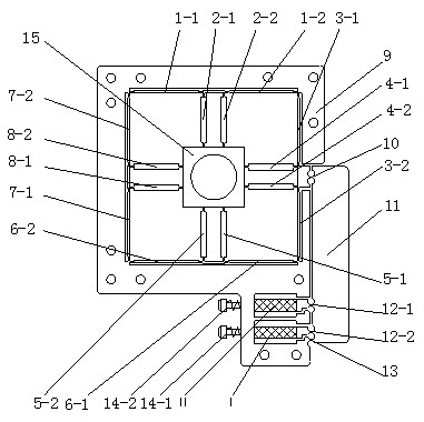
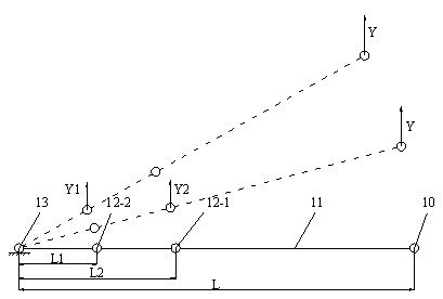
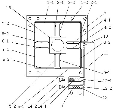
[0019] Such as figure 1 As shown, the present invention comprises a base 9, a variable magnification lever 11, a compound parallel four-bar guide mechanism and a motion platform 15; The flexible hinges 2-1, 2-2 of the fourth group of two parallel flexible hinges 4-1, 4-2, the fifth group of two parallel flexible hinges 5-1, 5-2 and the eighth group of two Parallel flexible hinges 8-1, 8-2 are distributed around the motion platform; where:

[0020] 1) One end of the first group of two flexible hinges 1-1, 1-2 is respectively hinged to the two ends of the first side of the base 9, and the other end of the first group of two flexible hinges 1-1, 1-2 is respectively connected to the One end of the second group of two parallel flexible hinges 2-1, 2-2 is hinged, and the other ends of the second group of two parallel flexible hinges 2-1, 2-2 are respectively connecte...


PUM


Abstract

The invention discloses a device for changing a route range of a jogged positioning platform. The device is composed of a base, a variable magnification time lever, a composite parallel four-rod guiding mechanism and a movable platform. Two parallel grooves are arranged below the base and two piezoelectric ceramic drivers are respectively placed in the respective grooves; the variable magnification time lever is downwards arranged in the middle of the base; and output hinges arranged at the upper part of the variable magnification time lever are hinged with the middle parts of two parallel flexible hinge parts and respectively enable two input hinges of the lower part of the variable magnification time lever to be contacted with the two piezoelectric ceramic drivers through a pre-fastening screw. The variable magnification time lever is provided with a fixed hinge to be connected with the base; and the two input hinges can independently receive input displacements of the piezoelectricceramic drivers to transmit the amplified displacements to the movable platform, and an output displacement of the platform has two route ranges, so that a composite route range function with a smallroute and a high precision or low precision requirements and greater route requirements are realized.

Description

technical field [0001] The invention relates to a micro-motion positioning device, in particular to a device for changing the stroke range of a micro-motion positioning platform. Background technique [0002] With the development of science and technology, there is an urgent need for submicron or even nanometer precision positioning technology in the fields of ultra-precision machining, microelectronics engineering, bioengineering, and nanotechnology. The existing micro-positioning platforms only have a displacement output range of a stroke. When the stroke is large, it is difficult to obtain a higher output displacement accuracy; in order to obtain a higher output displacement accuracy of the micro-positioning platform, the positioning platform The output displacement stroke tends to be smaller. Contents of the invention [0003] The purpose of the present invention is to provide a device for changing the travel range of a micro-motion positioning platform. [0004] The...

Claims


Application Information

Patent Timeline
IPC IPC(8): G12B5/00
Inventor 王文贺瑶卢科青
Owner ZHEJIANG UNIV
Why Eureka
Try Eureka