Orthodontics self-locking bracket

A self-locking bracket and orthodontic technology, applied in the field of dental orthodontic appliances, can solve problems such as affecting the orthodontic treatment effect, hindering the normal movement of the arch wire, etc., to achieve simple and smooth opening, reliable locking effect, and simple and convenient operation. Effect

Active Publication Date: 2012-09-26
ZHEJIANG PROTECT MEDICAL EQUIP
View PDF5 Cites 12 Cited by
  • Summary
  • Abstract
  • Description
  • Claims
  • Application Information

AI Technical Summary

Problems solved by technology

[0002] At present, the orthodontic treatment mainly uses steel wire ligation or rubber ring ligation. These two kinds of ligation generally apply force directly to the arch wire, which will generate greater pressure on the arch wire, hinder the normal movement of the arch wire, and easily affect the orthodontic treatment. Effect

Method used


Image

  • Orthodontics self-locking bracket
  • Orthodontics self-locking bracket
  • Orthodontics self-locking bracket

Examples


Embodiment Construction

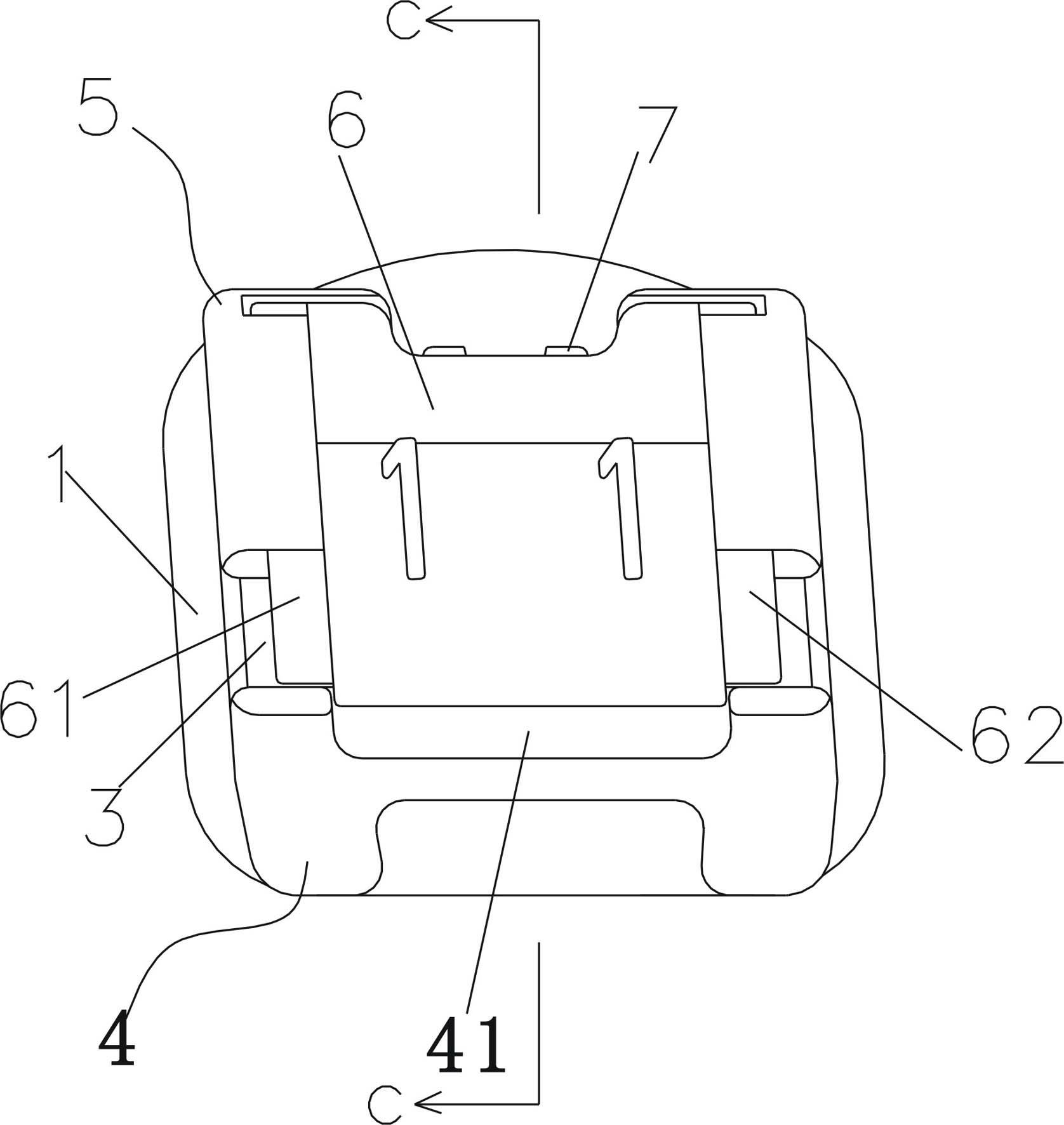
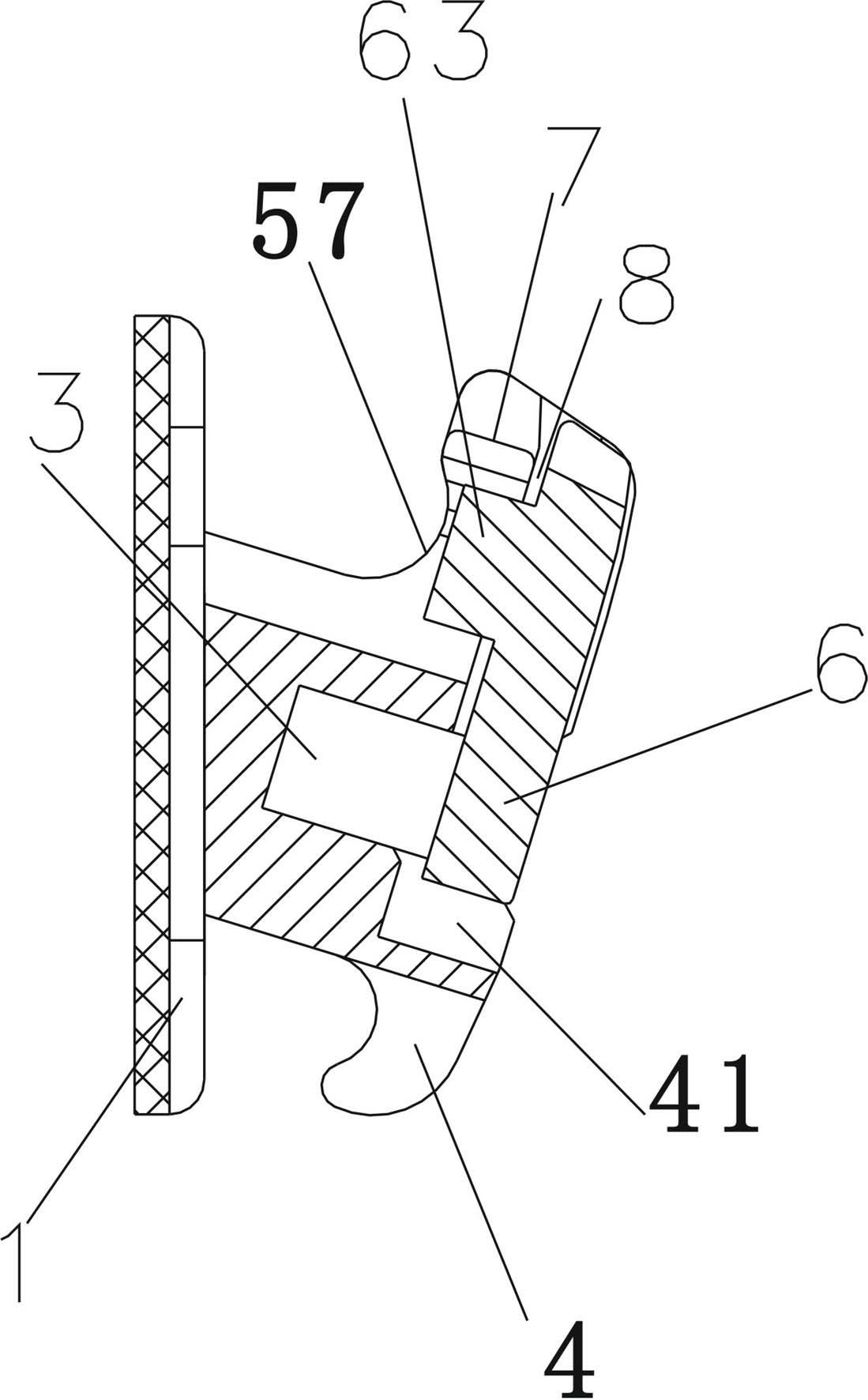
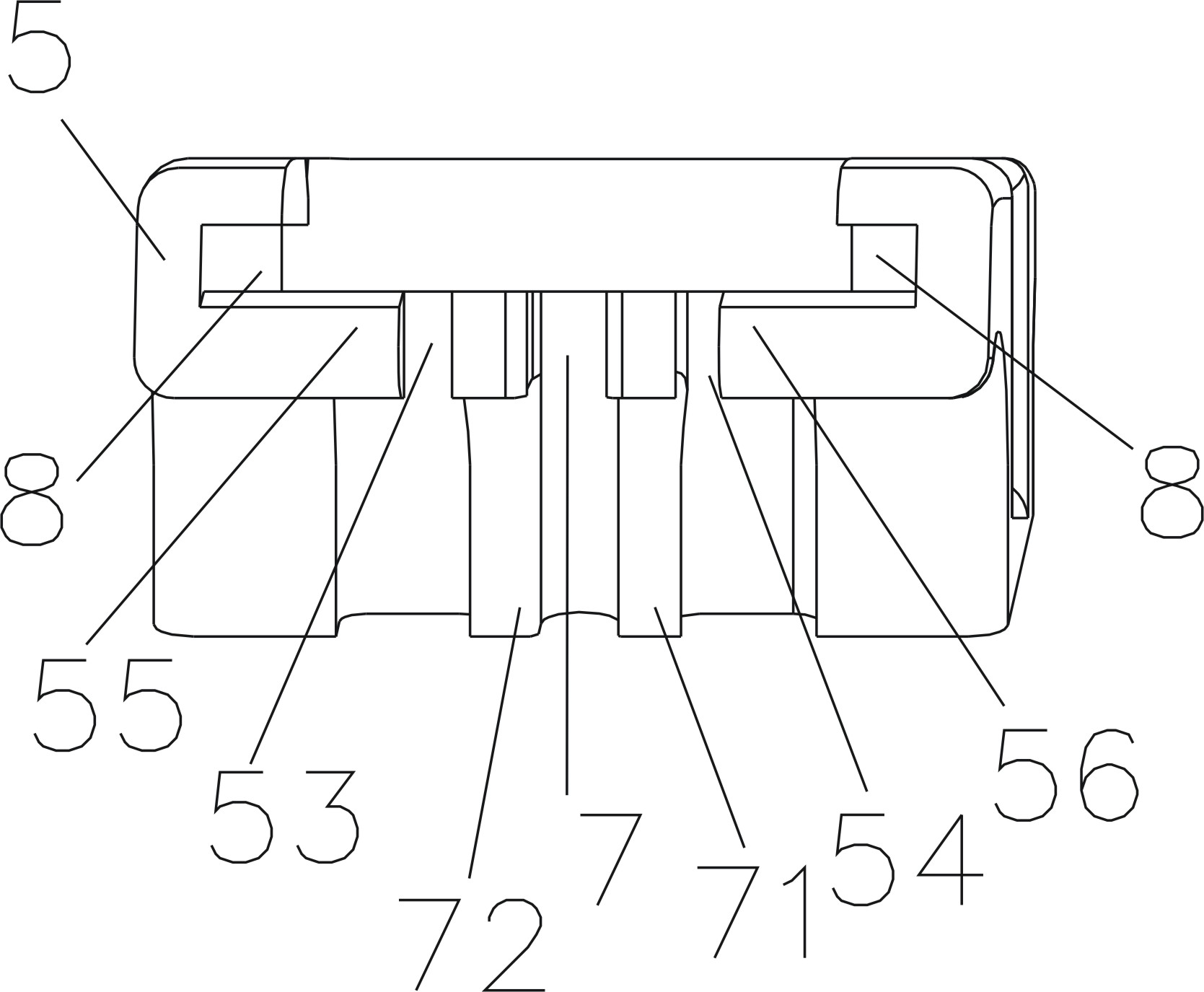
[0020] Such as figure 1 and figure 2 As shown, an orthodontic self-ligating bracket includes a base plate 1 and a bracket body with an archwire slot 3 , and the bracket body includes two separate working wings 4 and 5 . The working wing 4 and the working wing 5 are respectively located on both sides of the archwire slot 3 . Such as image 3 and Figure 4 As shown, a slot is arranged on the working wing 5, namely image 3 The area surrounded by abcd in the middle. A sliding locking piece 6 is arranged in the slot. The two sides of the sliding locking piece 6 are also respectively provided with slide bars 61, and the a end of the slotted ab side and the d end of the slotting cd side are respectively provided with a chute 8, so the sliding locking piece 6 can slide into the slotting , can also slide out from the slot. Such as Figure 5 As shown, the sliding locking piece 6 includes a piece 65, and a circular lock 63 and two positioning blocks 64 are arranged on the lower...


PUM


Abstract

The invention discloses an orthodontics self-locking bracket which comprises a base bottom plate and a bracket body with an arch wire slot, wherein the bracket body comprises two separated working wings which are located on the two sides of the arch wire slot respectively; the working wing on one side is provided with an open slot, and a sliding locking sheet is arranged in the open slot; the sliding locking sheet comprises a sheet body; a round latch and two positioning blocks are arranged on the lower surface of the sheet body; the two positioning blocks are located on the two sides of the round latch respectively; a round locking slot device matched with the round latch and two positioning blocks on the lower surface of the sheet body of the sliding locking sheet is arranged in the open slot; the round locking slot device comprises a round locking slot and two stop slide ways; the round locking slot is matched with the round latch; the two stop slide ways are in one-to-one matching with the two positioning blocks respectively; and the sliding locking sheet is used for covering the arch wire slot. The orthodontics self-locking bracket disclosed by the invention is convenient to operate.

Description

technical field [0001] The invention belongs to the field of dental orthodontic instruments, in particular to a bracket for dental orthodontics. Background technique [0002] At present, the orthodontic treatment mainly uses steel wire ligation or rubber ring ligation. These two kinds of ligation generally apply force directly to the arch wire, which will generate greater pressure on the arch wire, hinder the normal movement of the arch wire, and easily affect the orthodontic treatment. Effect. To solve this problem, Chinese patent ZL200620105725.8 has disclosed a bracket structure, the length of the ligature wing is shorter than the length of the working groove, so the ligature steel wire or the rubber ring no longer directly exerts force on the arch wire, and the arch wire can Move normally. However, the orthodontic brackets with this structure still cannot avoid the cumbersome steel wire or rubber ring ligation process. Contents of the invention [0003] Aiming at th...

Claims


Application Information

Patent Timeline
Patent Type & Authority Applications(China)
IPC IPC(8): A61C7/34
CPCA61C7/287
Inventor 王建均胡毅
Owner ZHEJIANG PROTECT MEDICAL EQUIP
Why Eureka
Try Eureka