Vacuum coating device

A vacuum coating and vacuum tank technology, applied in vacuum evaporation coating, sputtering coating, ion implantation coating, etc., can solve the problems of reducing the efficiency of chrome plating, and achieve the effects of improving coating quality, stable transmission, and reducing volume

Pending Publication Date: 2021-01-26
李县内
View PDF5 Cites 3 Cited by
  • Summary
  • Abstract
  • Description
  • Claims
  • Application Information

AI Technical Summary

Problems solved by technology

[0003] Existing coating devices, especially for coating parts such as end caps, have to reduce the number of single chrome-plating workpieces in order to ensure uniform coating and improve coating quality, thereby reducing the efficiency of chrome-plating. Therefore, we propose a vacuum coating device

Method used


Image

  • Vacuum coating device
  • Vacuum coating device
  • Vacuum coating device

Examples


Embodiment Construction

[0032]The technical solutions in the embodiments of the present disclosure will be clearly and completely described below in conjunction with the accompanying drawings in the embodiments of the present disclosure. Obviously, the described embodiments are only a part of the embodiments of the present disclosure, rather than all the embodiments. Based on the embodiments of the present disclosure, all other embodiments obtained by those of ordinary skill in the art without creative work shall fall within the protection scope of the present disclosure.

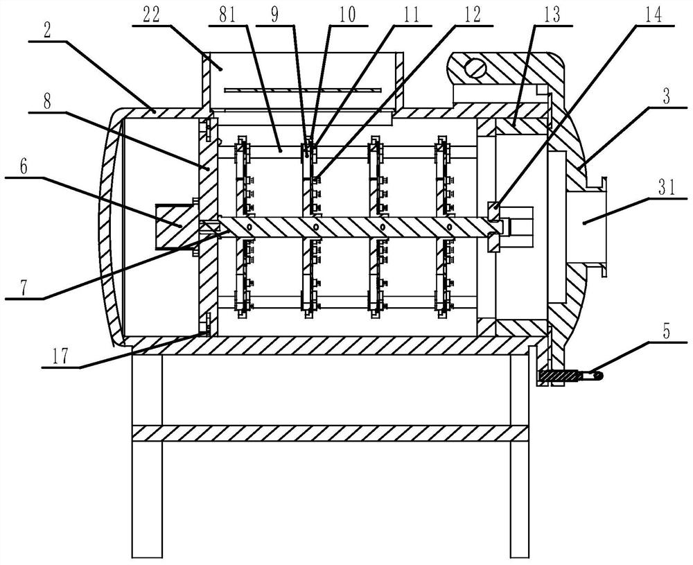
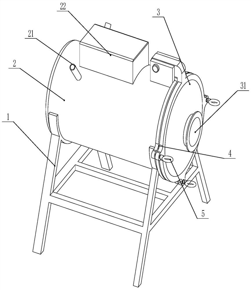
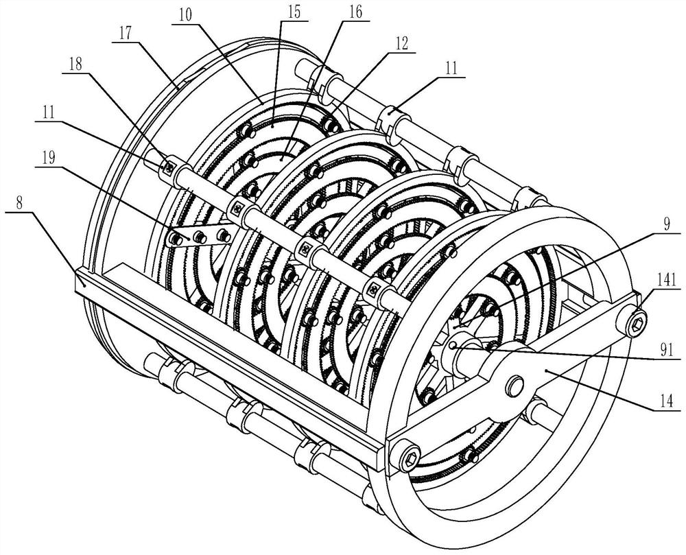
[0033]Seefigure 1 ~Fixed plate 14, in the embodiment of the present disclosure, a vacuum coating device, including a vacuum tank 2 and a metal ion bombardment bin 22 arranged on the top of the inner cavity of the vacuum tank 2 for bombarding metal, and used inside the vacuum tank 2 In the rotating bracket 9 for clamping the workpiece, a plurality of rotating brackets 9 are arranged in an array along the axial direction of the vacuum tank 2...


PUM


Abstract

The invention discloses a vacuum coating device, and relates to the technical field of vacuum coating. The vacuum coating device comprises a vacuum tank, a metal ion bombardment bin which is arrangedat the top of an inner cavity of the vacuum tank and is used for bombarding metal, and multiple rotating brackets which are arranged in the vacuum tank and are used for clamping workpieces; the multiple rotating brackets are distributed in the vacuum tank in the axis direction of the vacuum tank in an arrayed manner; the rotating brackets are detachably mounted on a rotating shaft and rotates along with the rotating shaft; a fixing plate is detachably and fixedly connected with a sliding bracket; multiple rotating supports are distributed on the end surface of the rotating brackets in the radially arrayed manner; rotatable first driving wheels are arranged between the adjacent rotating supports in the radial direction of the rotating brackets; the radially-adjacent first driving wheels onthe inner and outer sides of the first driving wheels are connected with the rotating supports in a meshing manner; inner gears are arranged on the outer sides of the outer circumferences of the rotating brackets; and the inner gears are connected with the rotating supports arranged on the outermost sides of the rotating brackets in a meshing manner. According to the vacuum coating device, the rotating supports are driven to rotate through gear meshing transmission, so that the workpieces are coated with films uniformly, and the film coating quality is improved.

Description

Technical field[0001]The present disclosure belongs to the technical field of vacuum coating, and specifically relates to a vacuum coating device.Background technique[0002]Vacuum coating is a technology that produces thin film materials by physical methods. In the vacuum chamber, the atoms of the material are separated from the heating source and hit the surface of the object to be plated. This technology was first used to produce optical lenses, such as nautical telescope lenses, etc.; later extended to other functional films, record aluminum plating, decorative coating and material surface modification, such as imitation gold plating on watch casings, mechanical tool coating, and changing processing Red hard. There are three forms of vacuum coating, namely evaporation coating, sputtering coating and ion plating.[0003]In order to ensure uniform coating and improve the quality of the coating, the existing coating device has to reduce the number of chromium-plated workpieces in a sin...

Claims


Application Information

Patent Timeline
Patent Type & Authority Applications(China)
IPC IPC(8): C23C14/50C23C14/28
CPCC23C14/505C23C14/28
Inventor 李县内
Owner 李县内
Why Eureka
Try Eureka