Axial side gap enlargement device for blade of disc shear

A technique of enlarging devices and discs, which is applied in the direction of shearing devices, shearing machine accessories, shearing machine equipment, etc., and can solve the problems of production line shutdown, large economic losses, and affecting the service life of side clearance adjustment devices, etc.

Active Publication Date: 2012-09-26
ANGANG STEEL CO LTD
View PDF4 Cites 0 Cited by
  • Summary
  • Abstract
  • Description
  • Claims
  • Application Information

AI Technical Summary

Problems solved by technology

In the process of adjusting the axial side clearance of the disc shears, a medium and heavy plate factory found that the maximum and minimum limit positioning of the axial side clearance device of the disc shears was not accurate, so that the shears often appeared The axial side clearance exceeds the limit range, resulting in the grinding of the side clearance adjustment device, which in turn causes the entire production line to stop production, which takes a long time to deal with the accident and causes great economic losses
[0003] The main reason for the inaccurate limit positioning of the axial side clearance device of the disc shears is that the range of the side clearance that can be adjusted by the axial side clearance adjustment device of the shear blade is small. During the adjustment process, the travel switch cannot play a good role in limit protection. When the side clearance adjustment device exceeds the limit position, it will cause the side clearance adjustment device to grind to death, which not only affects the service life of the side clearance adjustment device, but also causes Stop production accidents, troubleshooting is very difficult

Method used


Image

  • Axial side gap enlargement device for blade of disc shear
  • Axial side gap enlargement device for blade of disc shear
  • Axial side gap enlargement device for blade of disc shear

Examples


Embodiment Construction

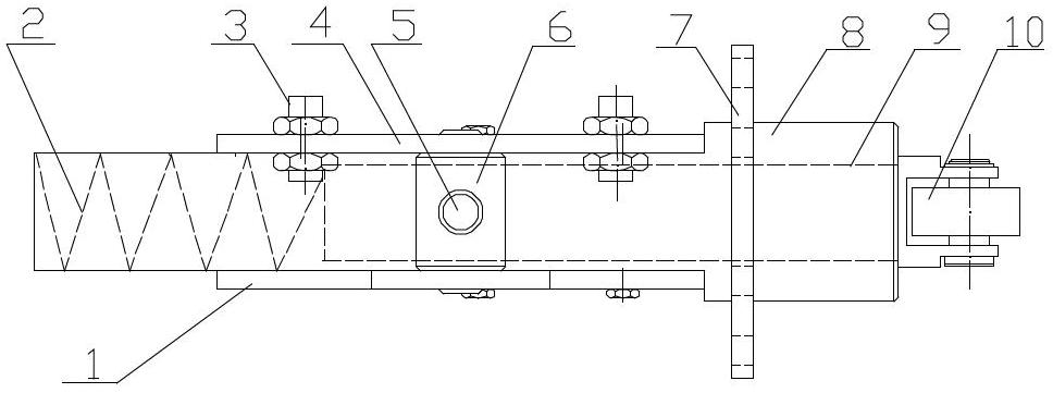
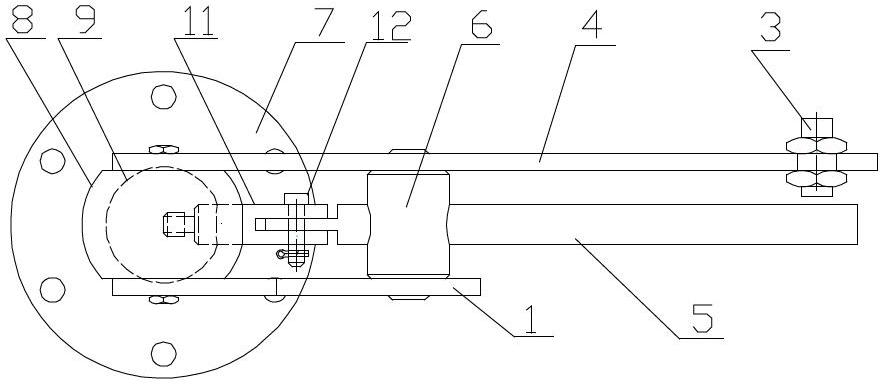
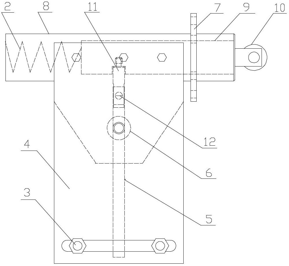
[0015] As can be seen from the accompanying drawings, the disc shear blade axial side clearance enlargement device of the present invention is composed of a lower support plate 1, a spring 2, a travel switch 3, an upper support plate 4, a swing rod 5, a rotating shaft 6, a flange 7, a slide Cover 8, slide bar 9, bearing 10, connecting rod 11, bearing pin 12 are formed.

[0016] Spring 2 is housed in the sliding sleeve 8, and the rear end of the sliding rod 9 is pressed against the spring 2, and the whole shaft is movably installed in the sliding sleeve 8, and can slide along the sliding sleeve 8 inner cavity. The front end of the slide bar 9 has a bearing 10, and the sliding sleeve 8 is connected to the body of the disc shears through the flange 7, so that the front end bearing 10 of the slide bar 9 leans against the shaft of the disc shears under the action of the spring 2. The middle part of slide bar 9 is provided with a connecting rod hole, and connecting rod 11 one ends a...


PUM


Abstract

The invention provides an axial side gap enlargement device for a blade of a disc shear. A sliding bar is arranged in a sliding sleeve with a spring, the sliding sleeve is connected to a disc shear body, and a bearing at the front end of the sliding bar is abutted against a disc shear blade shaft; the middle part of the sliding bar is connected with a connecting bar, a swinging bar penetrating through a through hole of a rotary shaft is movably connected with the connecting bar, the rotating shaft is movably connected to upper and lower supporting plates which are fixed on the upper surface and the lower surface of the sliding sleeve, and the other end of the upper supporting plate is provided with a travel switch. In the enlargement device, although the actual travel keeps unchanged during adjustment of a blade side gap, the range scope in the travel switch reflected by the swinging bar is enlarged by multiple times, thereby avoiding the exceeding of the extreme range of the blade side gap, preventing the seizing phenomenon of a blade side gap adjusting device, reducing the failure probability and accident handling time, prolonging the service life of the blade side gap adjusting device and effectively reducing the consumption of spare parts and production cost.

Description

technical field [0001] The invention belongs to the field of mechanical equipment, and in particular relates to a shear blade axial side clearance enlargement device suitable for disc shears in the finishing area of ​​steel plates. Background technique [0002] Disc shears are essential equipment on a strip or plate rolling production line. In the process of adjusting the axial side clearance of the disc shears, a medium and heavy plate factory found that the maximum and minimum limit positioning of the axial side clearance device of the disc shears was not accurate, so that the shears often appeared If the axial side clearance exceeds the limit range, the side clearance adjustment device will be grinded to death, which will cause the entire production line to stop production, which will take a long time to deal with the accident and cause great economic losses. [0003] The main reason for the inaccurate limit positioning of the axial side clearance device of the disc shea...

Claims


Application Information

Patent Timeline
IPC IPC(8): B23D33/00B23D19/00
Inventor 杨春雨党福元
Owner ANGANG STEEL CO LTD
Why Eureka
Try Eureka