Upright column structure of stacker

A stacker and column technology, applied in the field of column structure, can solve the problems of wasting materials and large column cross-sectional size, and achieve the effects of saving materials, simple structure and easy realization.

Active Publication Date: 2012-09-26
WUXI ZHONGDING INTEGRATION TECH CO LTD
View PDF7 Cites 2 Cited by
  • Summary
  • Abstract
  • Description
  • Claims
  • Application Information

AI Technical Summary

Problems solved by technology

[0003] The purpose of the present invention is to address the above problems and provide a stacker column structure to solve the problem that the traditional stacker column structure uses a rectangular tube. In order to ensure overall stability, the column cross-sectional size is large and the problem of material waste

Method used


Image

  • Upright column structure of stacker
  • Upright column structure of stacker
  • Upright column structure of stacker

Examples


Embodiment Construction

[0014] The technical solutions of the present invention will be further described below in conjunction with the accompanying drawings and through specific implementation methods.

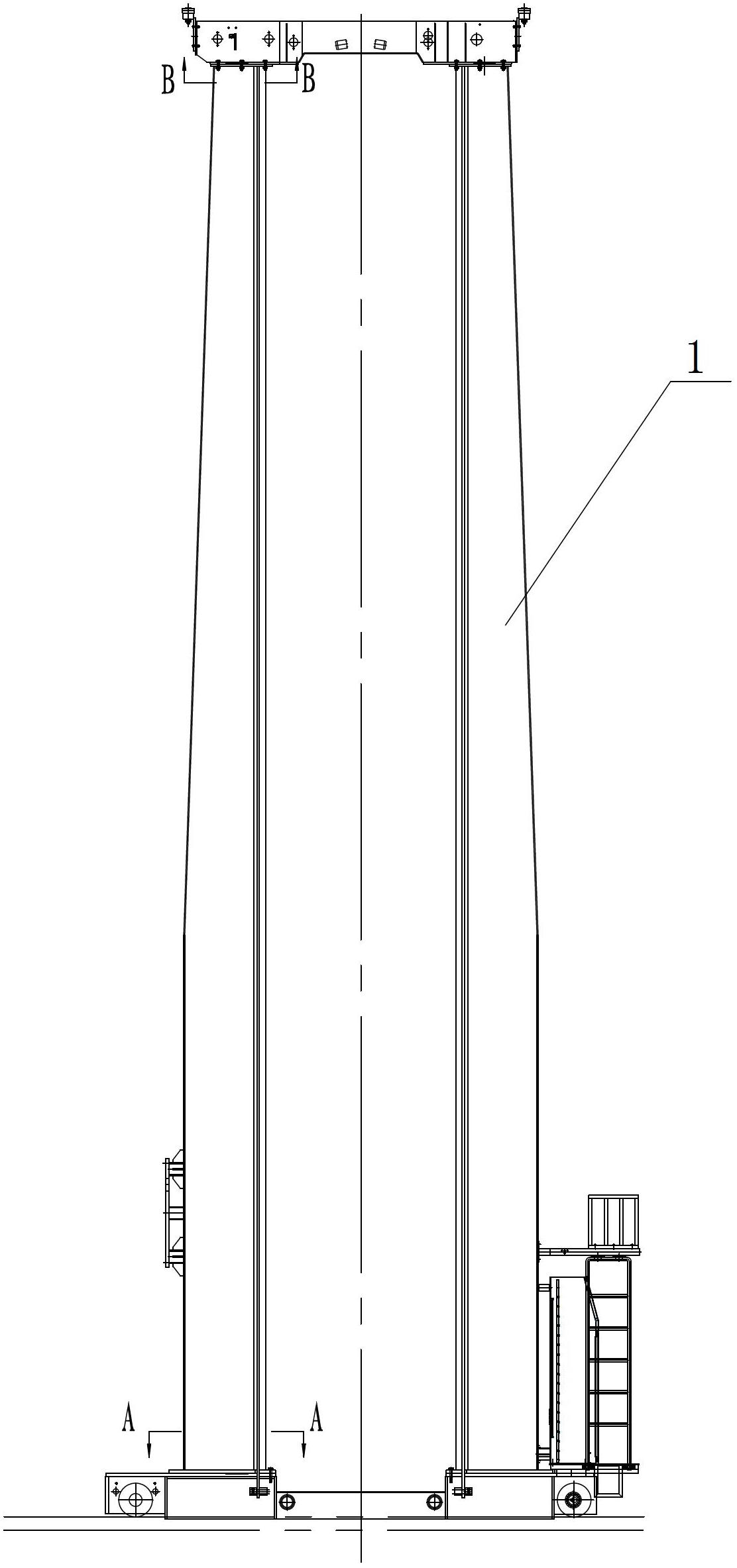
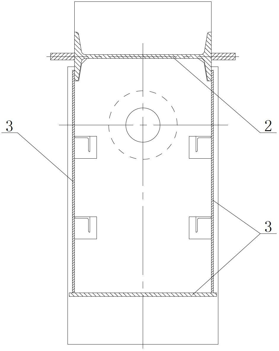
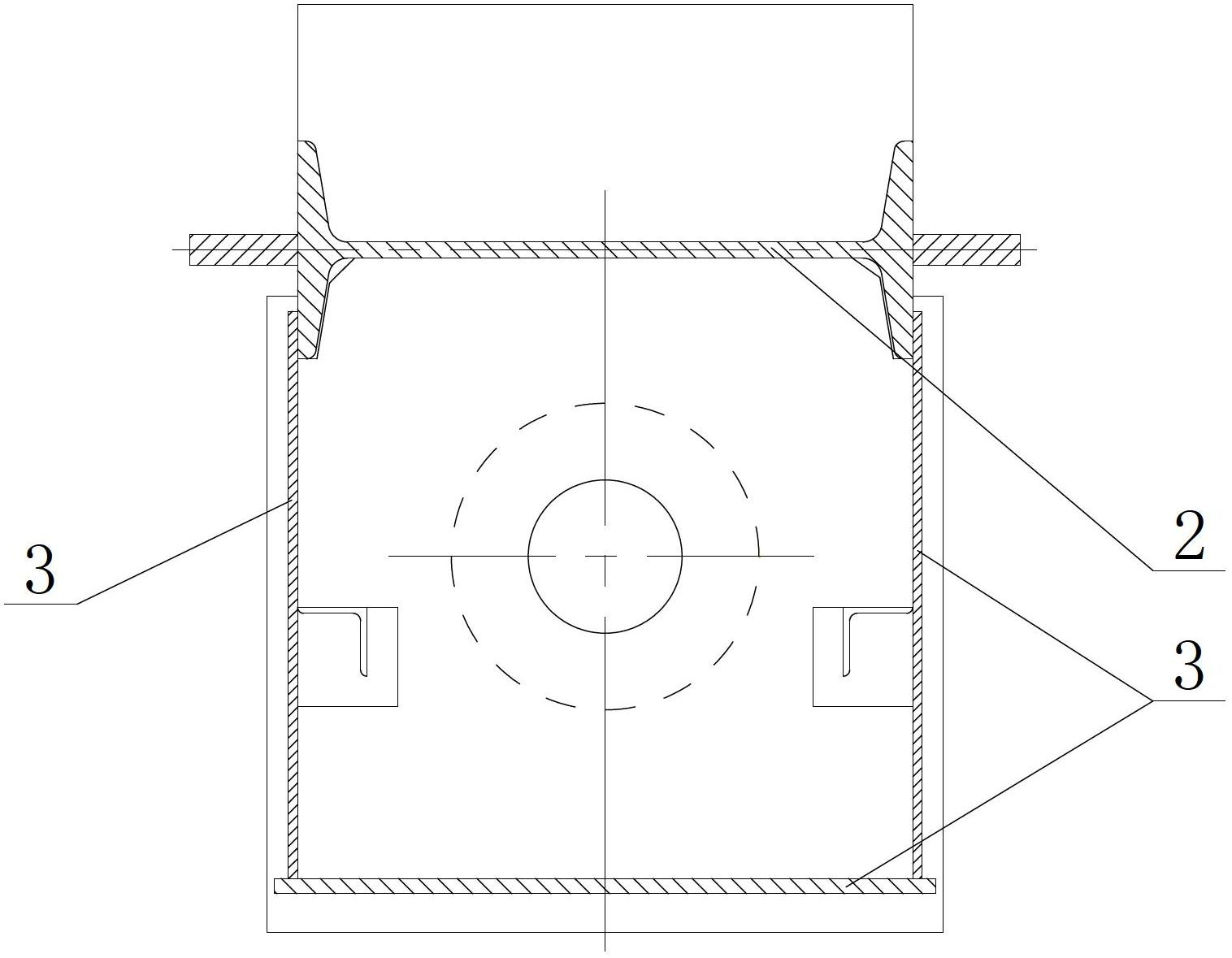
[0015] Please refer to Figures 1 to 3 as shown, figure 1 It is a structural schematic diagram of the column structure of the stacker of the present invention; figure 2 yes figure 1 The schematic cross-sectional view of the column structure of the stacker shown at A-A; image 3 yes figure 1 The schematic cross-sectional view of the column structure of the stacker shown at B-B. In this embodiment, a stacker column structure includes a column body 1, the column body 1 is formed by welding an I-shaped steel 2 and a steel plate 3, and its longitudinal section is a trapezoidal structure, and its cross-sectional area is from above increasing successively.

[0016] The cross-sectional area of ​​the column structure of the stacker increases sequentially from top to bottom. While ensuring that the win...


PUM


Abstract

The invention discloses an upright column structure of a stacker. The upright column structure comprises an upright column body, wherein the upright column body is formed by connecting I-steel and steel plates, and the cross sectional area of the upright column body is increased in sequence from top to bottom. The cross sectional area of the upright column structure of the stacker is increased in sequence from top to bottom, so that the deflection, the overall strength and the rigidity of the upright column body are ensured to meet requirements, materials are greatly saved, and the structure is simple and is easy to implement.

Description

technical field [0001] The invention relates to a column structure, in particular to a stacker column structure. Background technique [0002] At present, the cross-section of the general stacker column is consistent from top to bottom, and it can be directly made of profiles (rectangular tubes or I-beams) welded with flat steel guide rails, usually 300×400 rectangular tubes. However, this structure has limitations. When the height of the stacker is very large (height is greater than 25 meters), the weight of the entire equipment will be large, and the stability of the stacker will be a big problem when the stacker is running horizontally and the loading platform is lifted. When the loading platform is at the highest position, the upper part of the column has a large winding. If a conventional rectangular tube structure is used, in order to ensure the overall stability, the cross-sectional size of the column is required to be large, resulting in a large increase in material ...

Claims


Application Information

Patent Timeline
IPC IPC(8): B66F9/075B66F9/07
Inventor 张科翁忠杰
Owner WUXI ZHONGDING INTEGRATION TECH CO LTD
Why Eureka
Try Eureka