Lamp housing heat dissipation structure and lamp

A technology of heat dissipation structure and lamp housing, applied in the field of lighting, can solve the problems of increasing the size of lamps, shortening the life of electrical devices, and increasing the temperature of electrical devices, and achieves the effects of small size, improved heat dissipation performance, and reduced volume

Inactive Publication Date: 2014-01-15
OCEANS KING LIGHTING SCI&TECH CO LTD +1
View PDF1 Cites 0 Cited by
  • Summary
  • Abstract
  • Description
  • Claims
  • Application Information

AI Technical Summary

Problems solved by technology

Since the upper and lower shells are sealed as a cavity, there will be a fatal flaw, that is, the heat generated by the light source will directly increase the temperature of the electrical device, and excessive temperature will shorten the life of the electrical device; in order to improve the heat dissipation performance, it is necessary to The outer wall of the lamp housing is made larger to increase the heat dissipation area to meet the heat dissipation requirements of the lamp, and the direct consequence is to increase the volume of the lamp

Method used


Image

  • Lamp housing heat dissipation structure and lamp
  • Lamp housing heat dissipation structure and lamp
  • Lamp housing heat dissipation structure and lamp

Examples


Embodiment approach

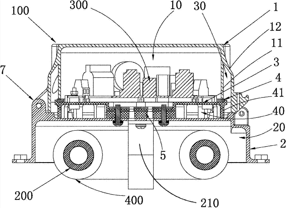
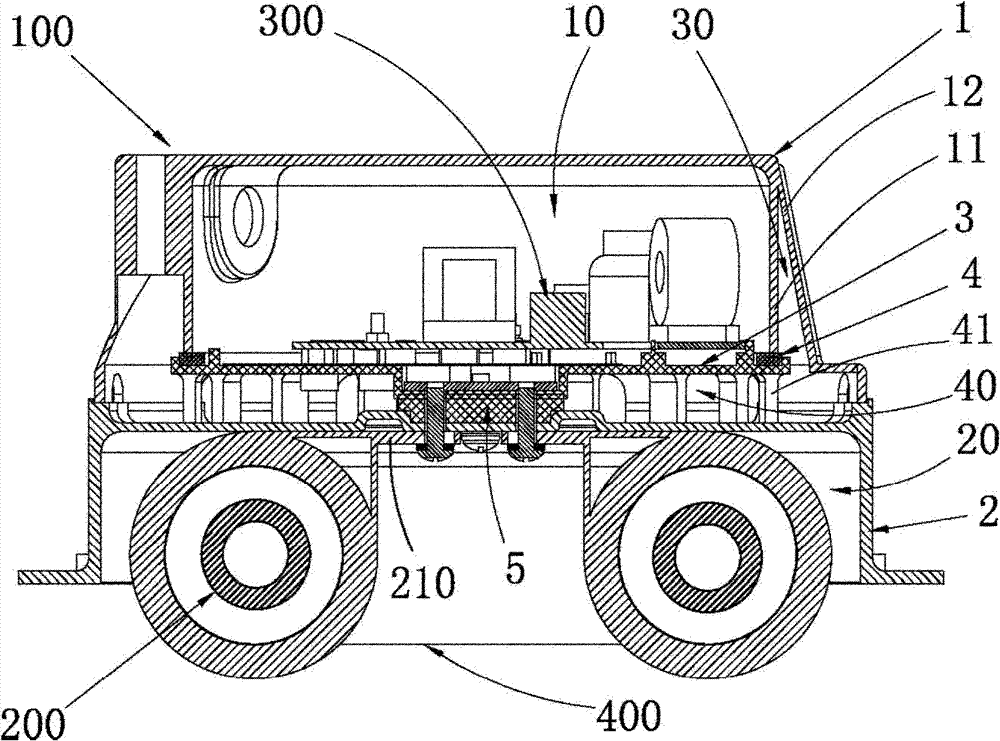
[0025] Further, see figure 1 and figure 2 , as an embodiment of the heat dissipation structure of the lamp housing provided by the present invention, the electrical appliance fixing plate 3 is connected to the lower casing 2, and the second sealing member 5 is arranged on the electrical appliance fixing plate 3 and the electrical appliance fixing plate 3 The connection of the lower case 2. The electrical appliance fixing plate 3 can also be connected with the upper casing 1, but it is not as convenient as connecting with the lower casing 2. At the same time, the electrical appliance fixing plate 3 is connected with the lower casing 2. When the upper casing 1 is opened, it is located on the electrical appliance fixing The electrical components on the board 3 are directly exposed outside, which is beneficial to the maintenance of the electrical components. Since the connection between the electrical appliance fixing plate 3 and the lower housing 2 uses bolts, there will be a ...

specific Embodiment approach

[0033] Further, see figure 2 , as a specific embodiment of the lamp provided by the present invention, a light source fixing seat 210 is arranged inside the lower casing 2, and the light source fixing seat 210 is assembled in direct contact with the lower casing 2 in a large area. The light source component 200 is disposed on the light source fixing seat 210 . In this way, the heat generated by the light source part 200 can be transferred to the light source fixing seat 210 through the most effective heat conduction method, and then transferred to the lower casing 2 and dissipated, so that the heat dissipation efficiency is improved.

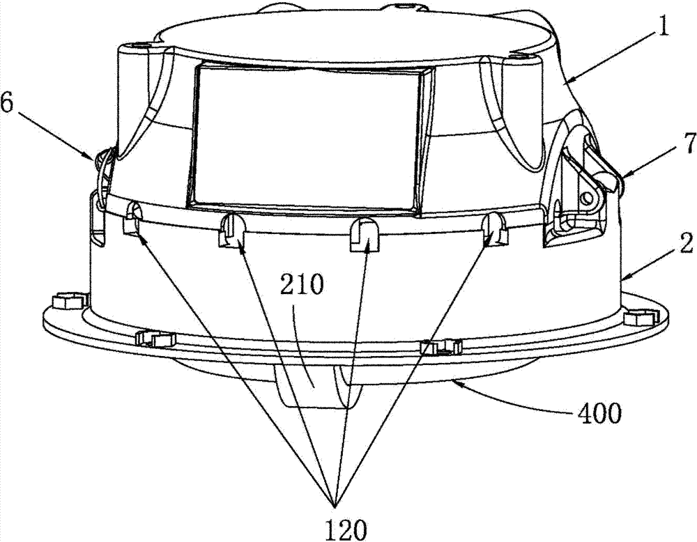
[0034] Further, see figure 1 and image 3 , as a specific embodiment of the lamp provided by the present invention, a transparent casing 400 for protecting the light source part 200 is also provided on the periphery 200 of the light source part. The transparent casing 400 can prevent foreign objects from directly contacting the light source ...


PUM


Abstract

The present invention is suitable for the technical field of lighting, and provides a lamp housing heat dissipation structure. The lamp housing heat dissipation structure comprises: an upper housing, and a lower housing connected with the upper housing; an electric appliance fixation plate capable of heat insulting disposed between the upper housing and the lower housing; the upper housing and the electric appliance fixation plate combined together through covering to form an electric appliance cavity , and an inner cavity of the lower housing being a light source cavity for installing a light source; a first sealing member disposed between the upper housing and the electric appliance fixation plate; and a second sealing member disposed between the lower housing and the electric appliance fixation plate. The present invention also provides a lamp, comprising a lamp housing, a light source component, and a ballast, wherein the lamp housing has the described heat dissipation structure; the light source component is disposed inside the light source cavity; and the ballast is disposed inside the electric appliance cavity and is fixed on the electric appliance fixation plate. The lamp housing heat dissipation structure utilizes the heat-insulated electric appliance fixation plate to separate the electric appliance cavity from the light source cavity, has a good heat dissipation effect, and guarantees service life of the lamp.

Description

technical field [0001] The invention belongs to the technical field of lighting, and more specifically relates to a lamp housing heat dissipation structure with good heat dissipation performance and a lamp adopting the lamp housing heat dissipation structure. Background technique [0002] Generally speaking, the greater the power of the lamp, the more heat it generates during work, so the higher the heat dissipation requirements, because the heat dissipation performance of the lamp directly affects the service life of the lamp itself. Generally, the lamp housing of the lamp adopts the upper and lower housing cover and airtight method, the heat generated by the light source part is conducted or radiated to the outer shell, and then the outer shell achieves the purpose of heat dissipation through heat exchange with the air. Since the upper and lower shells are sealed as a cavity, there will be a fatal flaw, that is, the heat generated by the light source will directly increase...

Claims


Application Information

Patent Timeline
Patent Type & Authority Patents(China)
IPC IPC(8): F21V29/00F21V17/10F21V19/00F21V15/02F21V31/00F21V29/10F21V29/83
Inventor 周明杰齐增智
Owner OCEANS KING LIGHTING SCI&TECH CO LTD
Why Eureka
Try Eureka