Note detecting/counting device and detecting/counting method

A counting device and counting method technology, applied in the financial field, can solve the problems of inaccurate counting processing, reduced ATM use efficiency, wrong judgment, etc., and achieve the effects of reducing the probability of misjudgment and improving the accuracy of banknote counting.

Active Publication Date: 2012-09-26
GRG BAKING EQUIP CO LTD
View PDF7 Cites 21 Cited by
  • Summary
  • Abstract
  • Description
  • Claims
  • Application Information

AI Technical Summary

Problems solved by technology

[0004] However, when the signal representing the presence or absence of banknotes is disturbed, especially when detecting banknotes with holes, such figure 1 Problem shown:
[0006] 2. Due to the interference of the hole 101, the sensor (such as the first sensor 201) counts the banknotes inaccurately
[0012] In the process of circulation, the state of banknotes gradually deteriorates, and banknotes are inevitably damaged. In addition, the currencies of some countries have the characteristics of window holes. For example, the plastic coins of some Southeast Asian countries have the characteristics of light-transmitting windows. When these have When banknotes with window features or damaged banknotes are transported in the channel, using the banknote processing device of the prior art to detect and count may make wrong judgments, thereby reducing the use efficiency of the ATM. Therefore, a more efficient method is needed. Reliable method and device for detecting and counting banknotes in transport

Method used


Image

  • Note detecting/counting device and detecting/counting method
  • Note detecting/counting device and detecting/counting method
  • Note detecting/counting device and detecting/counting method

Examples


Embodiment Construction

[0034] The following will clearly and completely describe the technical solutions in the embodiments of the present invention with reference to the accompanying drawings in the embodiments of the present invention. Obviously, the described embodiments are only some, not all, embodiments of the present invention. Based on the embodiments of the present invention, all other embodiments obtained by persons of ordinary skill in the art without creative efforts fall within the protection scope of the present invention.

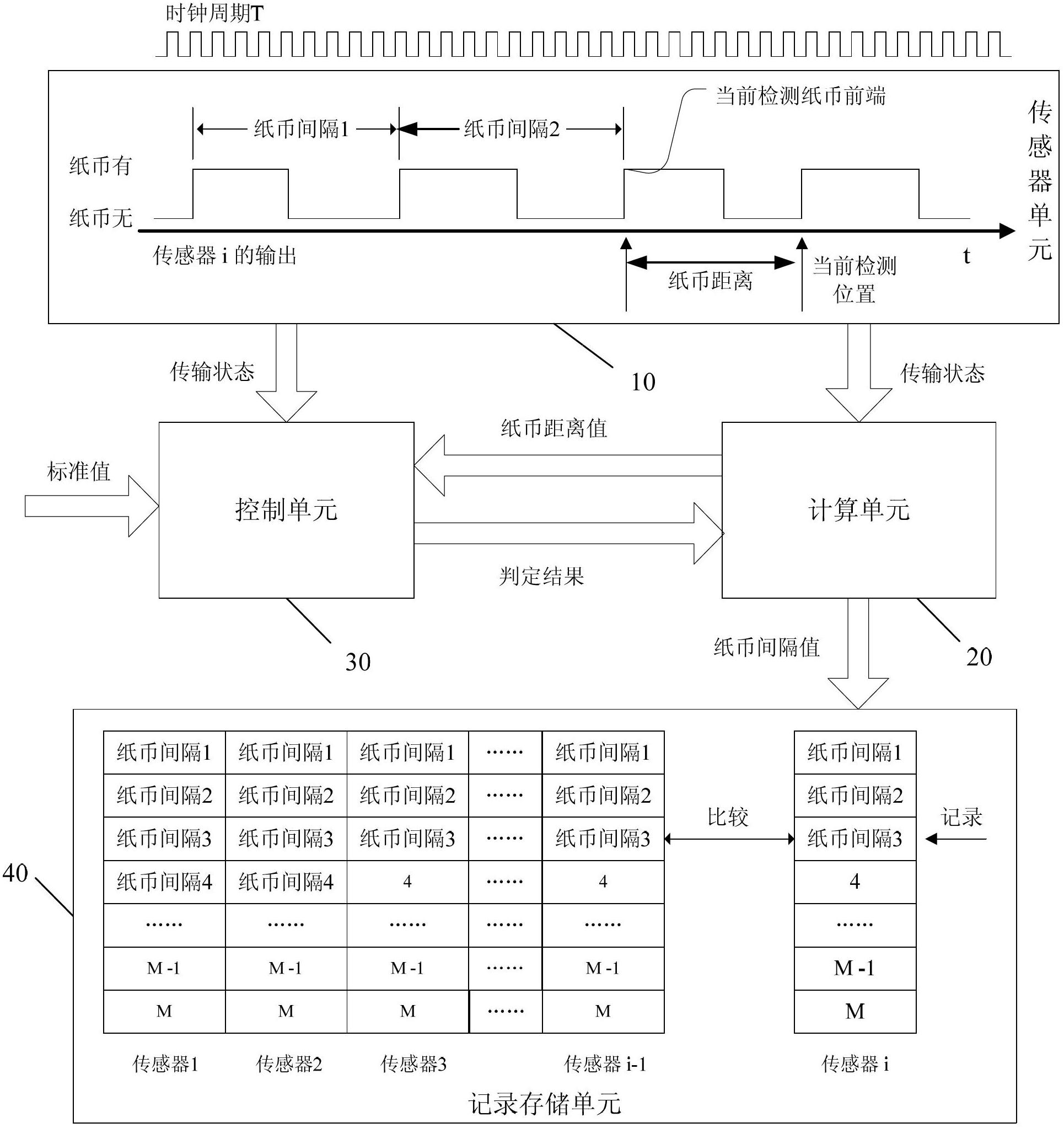
[0035] Please refer to figure 2 , The banknote detection and counting device of the present invention includes a sensor unit 10 , a calculation unit 20 , a control unit 30 and a record storage unit 40 .

[0036] Wherein, the sensor unit 10 is used to convert the output signals of multiple sensors distributed on the banknote conveying channel into a conveying state representing the presence or absence of banknotes according to a fixed clock cycle, wherein each sens...


PUM


Abstract

The invention discloses a note detecting / counting device which comprises a sensor unit, a computing unit and a control unit, wherein the sensor unit is used for converting output signals of multiple sensors distributed on a note transmission channel into transmission states representing whether a note exists, wherein each sensor is corresponding to a note counter; the computing unit is used for computing a note distance between the current detecting position of any sensor and the position of the front end of a currently detected note according to the transmission states output by the sensor unit; and the control unit is used for carrying out searching from the transmission states currently cumulatively output by the sensor unit once the note distance computed by the computing unit exceeds a note distance standard value, and when at least a transmission state representing that a note existence state is changed into a note absence state is searched, 1 is added to the count value of the note counter corresponding to the sensor, and when at least a transmission state representing that a note absence state is changed into a note existence state is searched, the fact that current notes are detected completely is determined, the position of the sensor (the note distance between the position of sensor and the front end of the currently detected note is closest to the note distance standard value) is taken as the position of the front end of a next detected note and the position is sent to the computing unit, so that the computing unit takes the position of the front end of the next detected note as a starting position so as to compute the next note distance. The invention also discloses a note detecting / counting method.

Description

technical field [0001] The present invention relates to the field of financial technology, in particular to a banknote detection and counting device and a detection and counting method for anti-interference detection of some broken banknotes or window banknotes by an automatic teller machine (called ATM). Background technique [0002] Optical sensors are generally used in ATMs to detect the transmission of banknotes in the channel. When a group of banknotes passes through the optical sensors in sequence, a set of transmission states will be generated to represent the presence or absence of banknotes. [0003] The usual banknote detection method is, when the sensor outputs the transmission state from non-existent, it is determined that the front end of the current banknote is detected, and the detection of the current banknote is started; or, when the sensor outputs the transmission state from presence to non-existence, it is determined that the After the back end of the bank...

Claims


Application Information

Patent Timeline
Patent Type & Authority Applications(China)
IPC IPC(8): G07D11/00G07D7/182
CPCG06M11/00G07D11/00G07D11/0084G07D7/185G07D7/17G07D11/50
Inventor 廖俊卿
Owner GRG BAKING EQUIP CO LTD
Why Eureka
Try Eureka