lift and method

A technology for elevators and elevator shafts, which is applied in the field of elevators for transporting people and/or goods, and achieves the effects of reliable stopper device and simple stopper device

Inactive Publication Date: 2016-04-27
KONE CORP
View PDF3 Cites 0 Cited by
  • Summary
  • Abstract
  • Description
  • Claims
  • Application Information

AI Technical Summary

Problems solved by technology

Another problem has been to actuate the stopper safely and reliably, i.e. to move the stopper to a relative position so that the stopper is on the impact path

Method used


Image

  • lift and method
  • lift and method
  • lift and method

Examples


Embodiment Construction

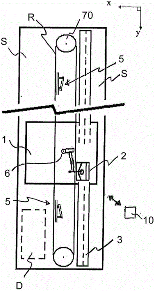
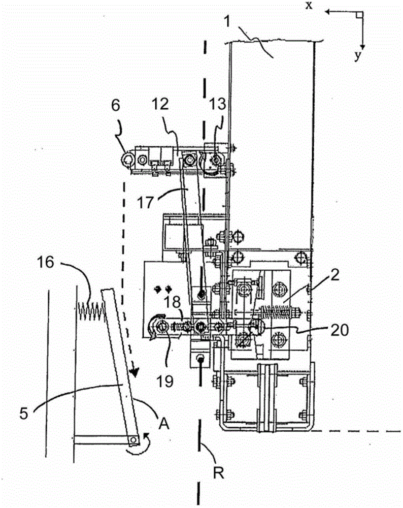
[0056] figure 1 An elevator according to the invention is shown comprising an elevator car 1 , an elevator shaft S and equipment for moving the elevator car (not shown), such as traction sheave machines and hoisting ropes supported on a building. The elevator car 1 comprises a brake 2 to which a movable mechanical stop 6 is connected, by moving the stop 6 the brake 2 is arranged to be turned into a braking position. The elevator shaft S includes a mechanical stop 5 . The stopper 6 on the elevator car is arranged to move between a position I where the stoppers 5, 6 are on the collision path and a position II where the stoppers 5, 6 are not in the collision on the route. When the stopper 6 is in position I after the elevator car 1 has moved towards the end of the elevator shaft a certain distance from this end, the stoppers 5 and 6 collide with each other. Thus, the stopper 6 is arranged to move by means of the supporting force of the stopper 5 in order to turn the brake 2 in...


PUM


Abstract

An elevator, which comprises an elevator car (1), which is arranged to move in the elevator hoistway (S), a brake (2) on the elevator car (1), a lever mechanism (12,17,18) connected to the brake (2), by- moving which lever mechanism in relation to the elevator car the brake (2) can be transferred to the braking position, a detent (5) in the elevator hoistway, a detent (6) on the elevator car, via which detent the aforementioned lever mechanism can be moved in order to cause braking of the brake (2), and which detents (5,6) on the elevator car and in the elevator hoistway can be brought, by moving at least one of the detents (5,6), to a relative position, in which the detents (5,6) are on a collision course. The elevator comprises - controllable means (7,8,9) for affecting the position of the detent (6), by controlling which means (7,8,9) the detent (6) can be moved between position I and position II, in which position I the detent (6) on the elevator car and the detent (5) in the elevator hoistway are on a collision course with each other, and in which position II the detents (5,6) are not on a collision course, - a control (10) for controlling the means (7,8,9).

Description

technical field [0001] The object of the invention is an elevator and a method for creating a safety space at the end of an elevator shaft, preferably an elevator suitable for transporting people and / or goods. Background technique [0002] A large number of different elevator safety devices are known from the prior art, with which a temporary safety space for maintenance personnel is realized at the end of the elevator shaft. Known in the prior art is, for example, a type of arrangement in which a movable stop in the elevator shaft is arranged to move into the passage of an actuated stop of a safety device provided on the elevator car middle. When the stoppers meet, the safety device on the elevator car moves to the braking position. The movement of the elevator car can thus be restricted for periods of time when the serviceman is on the roof of the elevator car or in the pit. Otherwise, maintenance personnel could easily be squeezed between the elevator car and the end o...

Claims


Application Information

Patent Timeline
Patent Type & Authority Patents(China)
IPC IPC(8): B66B5/00B66B5/16
CPCB66B5/0068B66B5/0075B66B5/22B66B1/46B66B5/16
Inventor K.肯佩南A.拉哈德约
Owner KONE CORP
Why Eureka
Try Eureka