electric working machine

A working machine and electric technology, applied in the direction of DC motor reduction gear, electric motor/converter plug, harvester, etc., can solve the problem of not being able to brake quickly

Active Publication Date: 2018-03-23
KOKI HLDG CO LTD
View PDF8 Cites 0 Cited by
  • Summary
  • Abstract
  • Description
  • Claims
  • Application Information

AI Technical Summary

Problems solved by technology

However, since there is no brake provided for the rotation of the cutting blade, the brake cannot be applied quickly when the trigger switch is released

Method used


Image

  • electric working machine
  • electric working machine
  • electric working machine

Examples


no. 1 example

[0040] Hereinafter, embodiments of the present invention will be described with reference to the accompanying drawings. In the drawings, the same reference numerals refer to the same elements, and a detailed description thereof will not be repeated. In addition, in this specification, front and rear, left and right, and up and down directions will be described based on the directions shown in the drawings.

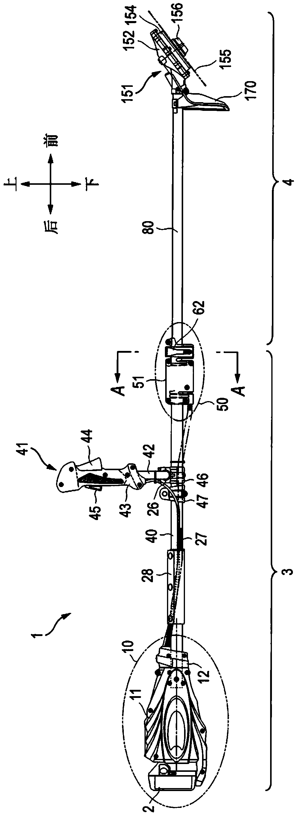
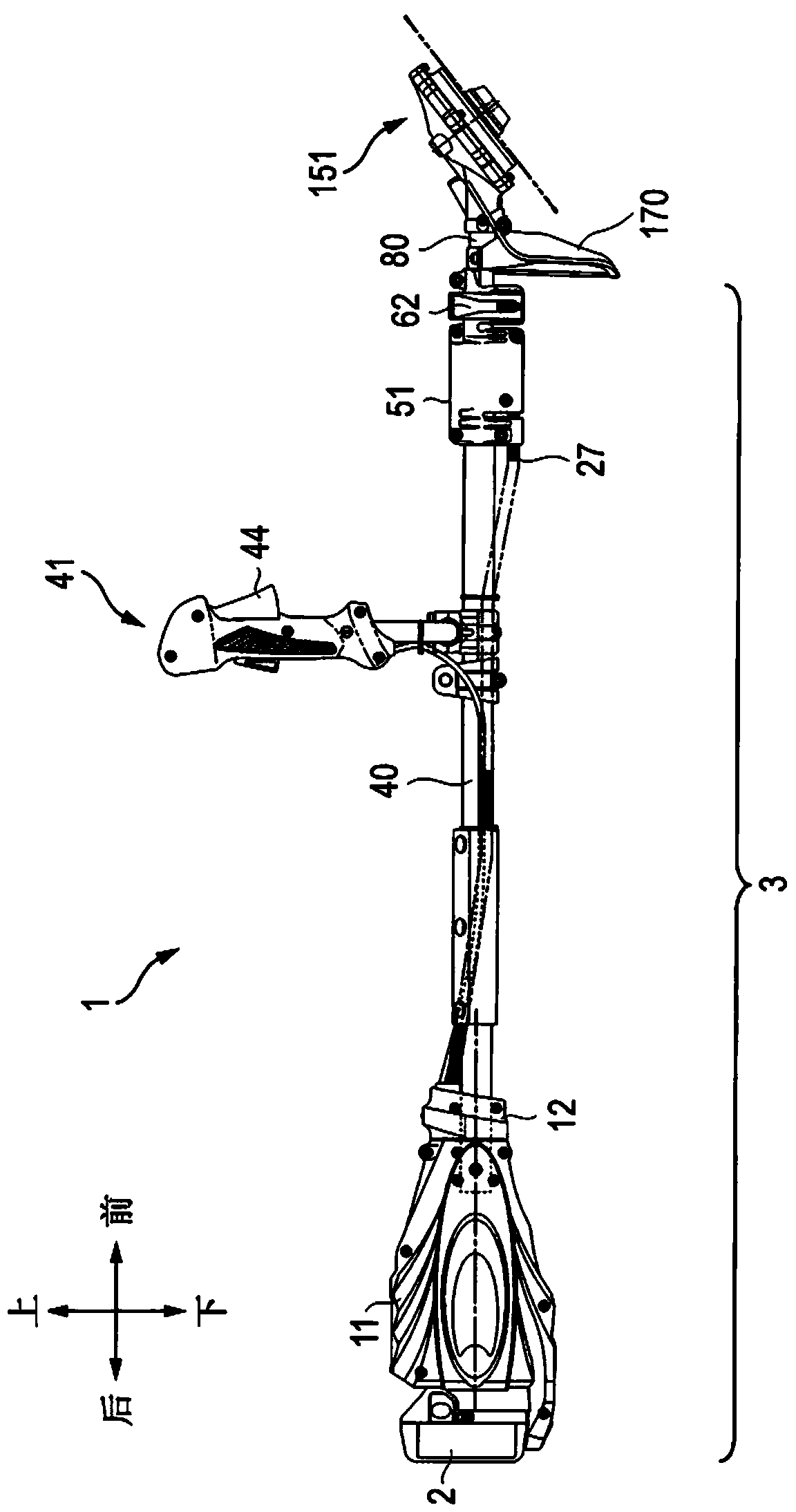
[0041] Such as figure 1 As shown, an electric brush cutter 1 as an example of an electric working machine includes: an operation unit 10 to which a battery pack 2 is attached; a retraction rod fixed to near the front end of the operation unit 10; a drive unit 151 to which to the end of the rod; and a handle unit 41 fixed to the vicinity of the center of the rod in the front-rear direction. In the current embodiment, the retractable rod includes a fixed tube 40 and a movable tube 80 connected to a front side of the fixed tube 40 and adapted to move relative to the fixed ...

no. 2 example

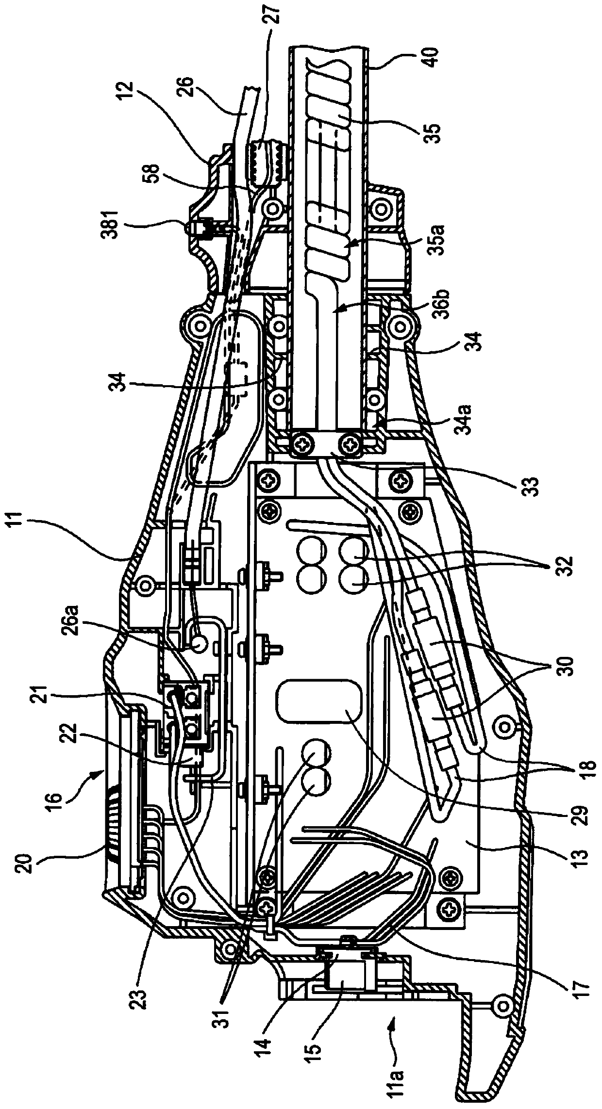
[0081] In the following, reference will be made to Figure 11 A circuit diagram according to a second embodiment of the present invention is described. The controller 301 according to the second embodiment is installed in such as image 3 On the circuit board 13 shown, the configuration or components other than the circuits mounted on the circuit board 13 are exactly the same as those described in the first embodiment. The controller 301 includes the same switch 21, main power switch circuit 214, main power automatic stop circuit 203, constant voltage circuit 207, battery voltage detection circuit 235, trigger detection circuit 240, and microcomputer 211 as in the first embodiment, and Duplicate descriptions about its internal configuration or behavior will therefore be omitted. The output stop circuit 343 is mainly in accordance with the output stop circuit 243 of the first embodiment (see Figure 7 ) operates in the same manner that the output stop circuit 343 receives a ...


PUM


Abstract

An electric working machine includes: a motor; a drive unit configured to be driven by the motor; a trigger switch configured to allow the motor to rotate; a power supply unit configured to supply power to the motor; a control unit configured to control the rotation of the electric motor, characterized in that the electric working machine further includes a switching element configured to short-circuit between terminals of the electric motor to apply electronic braking, In this case, the control unit is designed to regulate the brake by controlling the switching element when the electric machine is stopped.

Description

technical field [0001] Aspects of the present invention relate to an electric working machine driven by a motor. Background technique [0002] As a working machine for cutting grass or plants, there is known a bush cutter in which a rotary blade is driven. While brush cutters using an internal combustion engine as a power source are generally used, recently electric brush cutters are actually and widely used due to improved performance of rechargeable batteries. If electricity is used as the power source for the bush cutter, it is characterized by being quiet and exhaust-free, and has excellent running costs. Such an electric bush cutter is disclosed in Patent Document 1, in which the number of revolutions of the motor can be adjusted. will refer to Figure 17 The construction of such an electric bush cutter according to the prior art is described. In the electric bush cutter 1001 driven by a battery pack 1002, a motor unit 1004 is attached to the distal end of a tubular ...

Claims


Application Information

Patent Timeline
Patent Type & Authority Patents(China)
IPC IPC(8): H02P3/14
CPCH02P3/14H02P7/29A01D34/90H02P3/12
Inventor 中野恭嗣堀江由季富田博久船桥一彦
Owner KOKI HLDG CO LTD
Why Eureka
Try Eureka