Electromagnetic brake motor with spiral blade fan

A helical blade, electromagnetic braking technology, applied in electric components, control mechanical energy, electromechanical devices, etc., can solve problems such as affecting the service life of electric motors and friction disc electromagnetic components, failing to break through the single friction disc braking, and increasing the difficulty of product production. , to achieve the effect of good braking capacity, simple structure and low cost

Inactive Publication Date: 2012-11-21
宁波市镇海电机有限公司
View PDF1 Cites 0 Cited by
  • Summary
  • Abstract
  • Description
  • Claims
  • Application Information

AI Technical Summary

Problems solved by technology

It adopts a braking method in which the friction disc is fixedly connected to the motor shaft. The friction disc rotates together with the shaft, and its friction surface is a conical surface, which has a good braking effect, but it does not break through the single braking function of the friction disc. It cannot effectively solve the problem of the large amount of heat generated by the motor’s work and braking friction, which seriously affects the service life of the motor, friction disc, and electromagnetic components. If heat dissipation is required, an additional fan is required, which not only increases the manufacturing cost of the motor, but also improves Not only increases the production difficulty of the product, but also causes the volume of the motor to be huge and bloated

Method used


Image

  • Electromagnetic brake motor with spiral blade fan
  • Electromagnetic brake motor with spiral blade fan
  • Electromagnetic brake motor with spiral blade fan

Examples


Embodiment Construction

[0021] Embodiments of the present invention will be further described in detail below in conjunction with the accompanying drawings.

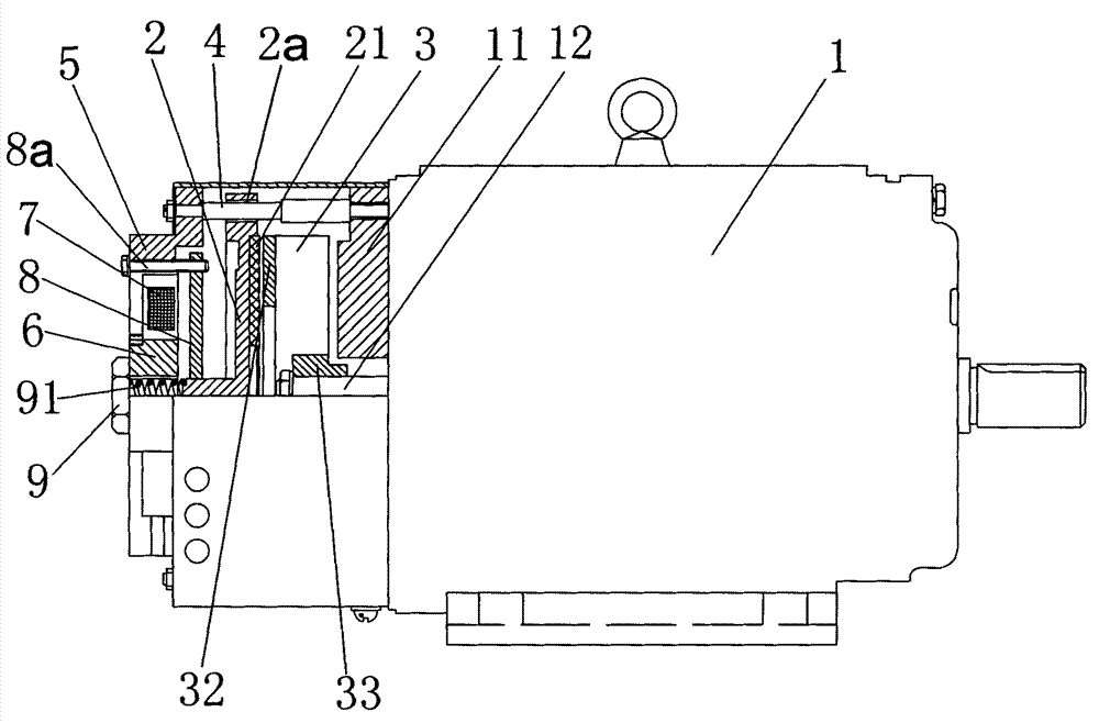
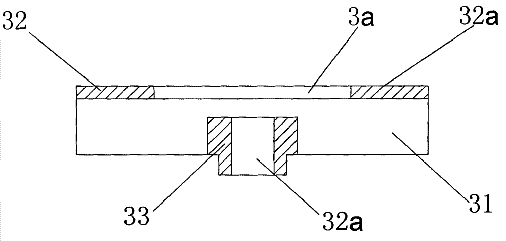
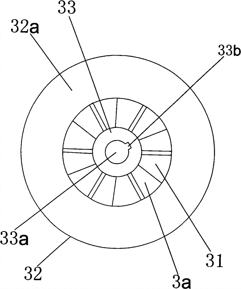
[0022] Figure 1 to Figure 5 Shown as the structural representation of the present invention.

[0023] The reference signs are: motor 1, rear end cover 11, rotating shaft 12, brake disc 2, guide slide hole 2a, asbestos brake plate 21, motor fan 3, air inlet cavity 3a, spiral blade 31, annular Disc 32, braking surface 32a, connecting protrusion 33, assembly through hole 33a, metal keyway 33b, column end cover screw 4, electromagnetic jacket 5, electromagnetic column core 6, electromagnetic coil 7, electromagnetic sucker 8, positioning screw 8a, adjusting bolt 9, pressure spring 91.

[0024] like Figure 1 to Figure 5 As shown, the electromagnetic brake motor with spiral blade fan of the present invention includes an electromagnetic brake fixedly connected to the rear end cover 11 of the motor 1, the electromagnetic brake is slidingly equipped...


PUM


Abstract

The invention discloses an electromagnetic brake motor with a spiral blade fan. The electromagnetic brake motor comprises an electromagnetic brake which is fixedly connected with the back end cover of a motor; the electromagnetic brake is provided with a brake disc in a sliding way; the rotating shaft of the motor is extended out of the back end cover of the motor; the shaft end of the rotating shaft of the motor is fixedly sleeved with a motor fan which is rotated integrally with the rotating shaft; the motor fan is provided with at least two spiral blades with spiral inclination angles; oneside surface of each spiral blade is connected with an annular disc which is coaxial with the rotating shaft; a brake surface is reserved on each annular disc; and the brake discs and the brake surfaces are in friction brake. The electromagnetic brake motor breaks through conventional fixed thoughts, utilizes the spiral blades of a fan as the brake surfaces, has very high brake performance and radiating and cooling effects, integrates double functions of braking and cooling, can ensure each part of the motor at a safe operating environmental temperature, and prolongs the service life of equipment.

Description

technical field [0001] The invention relates to the technical field of the motor industry, in particular to the motor technology using a motor fan to realize heat dissipation and braking, in particular to an electromagnetic braking motor with a spiral blade fan. Background technique [0002] In the derivative series of three-phase asynchronous motors, electromagnetic brake motors are widely used. However, the standard electromagnetic brake motors currently on the market have certain limitations in their structure. The brake is designed to act on the motor end cover, so its The braking effect and the braking speed are not ideal enough. For example, the Chinese invention patent, patent No. 01272633.8, discloses an electromagnetic braking device for a motor, which includes an electromagnet that is fixedly connected to the outside of the motor rear end cover through a connecting bolt, and there is a gap between the motor rear end cover and the electromagnet , There is an armatu...

Claims


Application Information

Patent Timeline
Patent Type & Authority Patents(China)
IPC IPC(8): H02K7/102H02K9/06
Inventor 张安琪
Owner 宁波市镇海电机有限公司
Why Eureka
Try Eureka