Synchronous valve in use for brake system

A brake system and synchronous valve technology, applied in the direction of pipeline layout, etc., can solve the problems that residual air cannot be discharged, the brake system and synchronous valve cannot work safely and reliably, and achieve improved braking performance, simple structure and reliability strong effect

Inactive Publication Date: 2010-03-24
WUHU SHENGLI TECH SHARES
View PDF6 Cites 0 Cited by
  • Summary
  • Abstract
  • Description
  • Claims
  • Application Information

AI Technical Summary

Problems solved by technology

Its disadvantage is that after braking, there is always a certain amount of residual air in the air supply port and in the brake chamber that cannot be discharged.
Seriously lead to the inability of the entire braking system and the synchronous valve to work safely and reliably

Method used


Image

  • Synchronous valve in use for brake system

Examples


Embodiment Construction

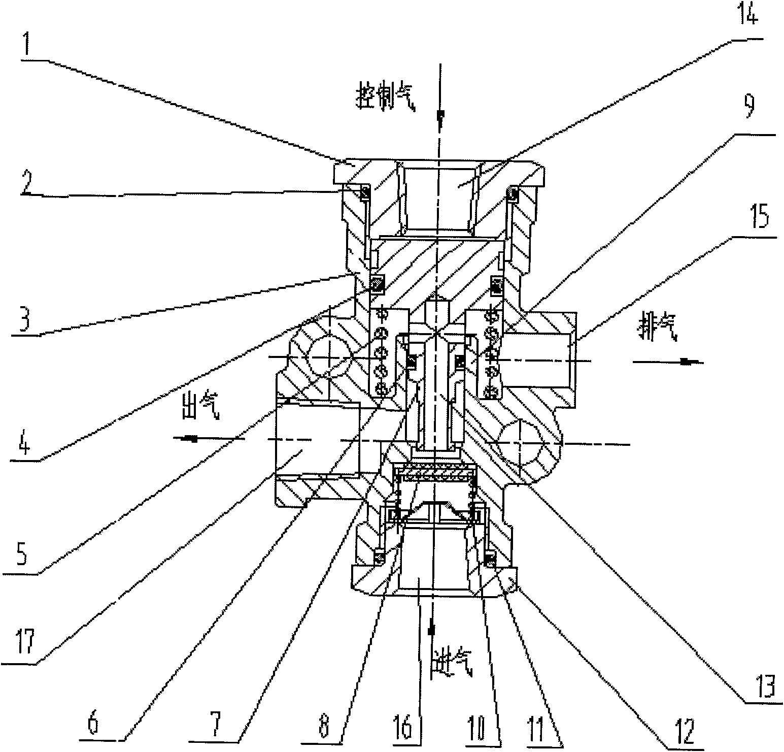
[0013] exist figure 1 Among them, a synchronous valve includes a valve body 3, on which there is an air inlet 16, an air outlet 17 and a control air port 14; an air inlet valve is arranged in the valve body 3 at one end of the air inlet 16; The air valve is opened, and the air inlet 16 is connected with the air outlet 17; the piston 7 that controls the work of the air inlet valve is arranged in the valve body 3 at one end of the control air port 14, and the upper stroke dead point of the piston 7 is adjustable and tightened on the control air port end. The control air port screw plug 1 is limited, the downstroke dead point of the piston 7 is on the inner step 9 of the valve body 3 at the control air port end, and the bottom of the piston 7 and the bottom of the valve body 3 at the control air port end press the return spring 5; fit on the valve body 3 Discharge port 15 is also provided with piston 7 return spring 10 position, and air passage 13 is also provided with in piston ...


PUM


Abstract

A synchronous valve for brake system has a valve body with air inlet, air outlet and control opening, an air inlet valve in said air inlet and opened when the car is running, a piston in said controlopening for controlling said air inlet valve and several sealing rings. Said piston has an internal air channel for exhausting the residual air from braking tube, a screw plug for regulating its top limit position, and a restoring spring under its bottom.

Description

technical field [0001] The invention relates to a synchronous valve for a vehicle braking system, in particular to a synchronous valve for a heavy-duty vehicle braking system. Background technique [0002] As we all know, the shortcomings of the braking system of heavy-duty vehicles, especially tractors, are that due to the length of the vehicle body and the length of the braking system pipeline, the brakes of the front, middle (rear) cars and trailers are not synchronized, and the braking distance is long. , Brake lag, serious can lead to the tragedies of vehicle overturning, car crash and death, bring immeasurable loss to life and property. Chinese patent CN89108201.8 discloses a vehicle air brake system and its valve, in which a synchronous valve is disclosed, which has an air supply port, an air supply port and a control port. There is a synchronous piston sleeved with a return spring in the cylinder body at the control port, and the lower end of the synchronous piston ...

Claims


Application Information

Patent Timeline
Patent Type & Authority Patents(China)
IPC IPC(8): B60T17/04
Inventor 欧腊英左新珍乔跃平叶新年王华
Owner WUHU SHENGLI TECH SHARES
Why Eureka
Try Eureka