
Improved laser annealing device

A technology of laser annealing and equipment, applied in laser welding equipment, welding equipment, metal processing equipment and other directions, can solve the problems of affecting the passage of laser beam 30 and increase the cost, and achieve the effect of reducing replacement and reducing cost

Inactive Publication Date: 2012-10-03
SHENZHEN CHINA STAR OPTOELECTRONICS TECH CO LTD
View PDF5 Cites 8 Cited by
  • Summary
  • Abstract
  • Description
  • Claims
  • Application Information

AI Technical Summary

Problems solved by technology

After the annealing equipment runs for a long time, debris 40 will accumulate on the lower surface of the laser beam output window 10 to make it opaque, thereby affecting the passage of the laser beam 30, and then the laser beam output window 10 needs to be replaced frequently, resulting in an increase in cost

Method used


Image

  • Improved laser annealing device
  • Improved laser annealing device
  • Improved laser annealing device

Examples


Embodiment Construction

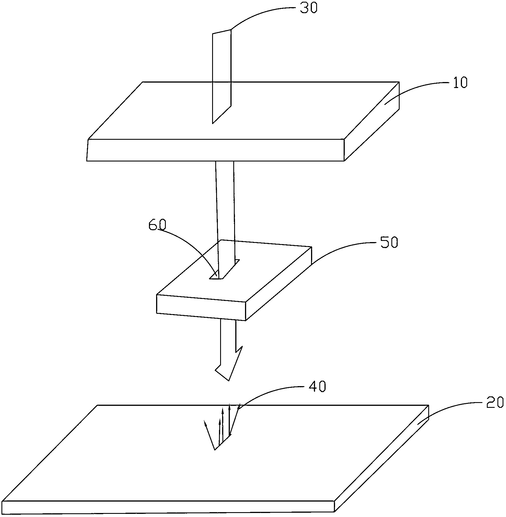
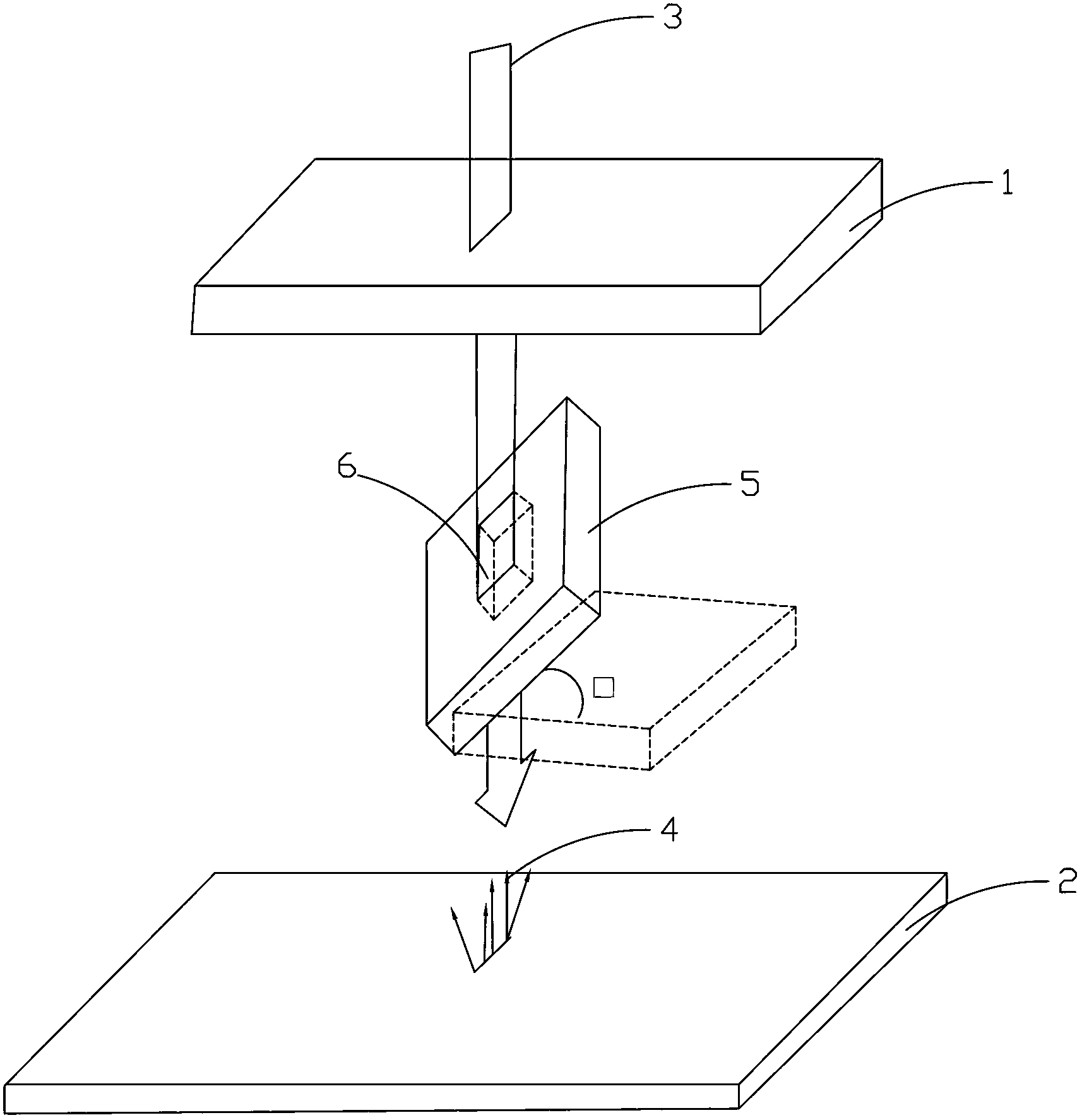
[0022] see figure 2 , which is a structural schematic diagram of a preferred embodiment of the improved laser annealing equipment of the present invention. The improved laser annealing equipment of the present invention comprises a laser beam 3, a casing (not shown), a laser beam output window 1 positioned at the top side of the casing, a substrate 2 positioned at the bottom side of the casing for carrying materials to be annealed, and a A movable protective block 5 between the laser beam output window 1 and the substrate 2, the protective block 5 is inclined with an inclination angle θ with respect to the horizontal direction, and in this preferred embodiment is 45° with the horizontal / vertical direction, On the one hand, it can protect the laser head, and on the other hand, it can reflect the splashed debris4. The protective block 5 is provided with a slit 6 passing through its upper and lower surfaces, and the laser beam 3 passes through the laser beam output window 1 ver...


PUM

PropertyMeasurementUnit
sizeaaaaaaaaaa

Abstract

The invention relates to an improved laser annealing device. The improved laser annealing device comprises a laser beam, a shell, a laser beam output window on the top side of the shell, a substrate on the bottom side of the shell for bearing a material to be annealed, and a moveable protective block between the laser beam output window and the substrate. The protective block is arranged obliquely relative to the horizontal direction and is provided with a slit passing through the upper and lower surfaces of the protective block. The laser beam is maintained to pass through the slit after passing through the laser beam output window vertically downward and is then sent to the substrate. The improved laser annealing device provided by the invention prevents fragments from affecting a laser head by arranging the protective block obliquely relative to the horizontal direction, thereby reducing the change of the laser head and lowering the cost.

Description

technical field [0001] The invention relates to annealing technology, in particular to an improved laser annealing equipment. Background technique [0002] Annealing is a commonly used metal heat treatment process, which refers to slowly heating the metal to a certain temperature, keeping it for a sufficient time, and then cooling it at an appropriate speed. The purpose of annealing is generally to: reduce hardness, improve machinability; eliminate residual stress, stabilize size, reduce deformation and crack tendency; refine grain, adjust structure, and eliminate structure defects. [0003] It is also often applied to annealing technology in semiconductor technology. For example, semiconductor chips require annealing after ion implantation. Because when implanting impurity ions into the semiconductor, the high-energy incident ions will collide with the atoms on the semiconductor lattice, causing some lattice atoms to shift, resulting in a large number of vacancies, which ...

Claims


Application Information

Patent Timeline
Patent Type & Authority Applications(China)
IPC IPC(8): B23K26/073B23K26/16H01L21/268
CPCB23K26/073H01L21/268B23K26/16B23K26/0732B23K26/066B23K26/354B23K26/706
Inventor 王烨文
Owner SHENZHEN CHINA STAR OPTOELECTRONICS TECH CO LTD
Features
  • Generate Ideas
  • Intellectual Property
  • Life Sciences
  • Materials
  • Tech Scout
  • Unparalleled Data Quality
  • Higher Quality Content
  • 60% Fewer Hallucinations
Learn More