Ring beam support

A technology of ring beams and support seats, applied in auxiliary devices, auxiliary welding equipment, welding/cutting auxiliary equipment, etc., can solve the problems of complex shape and large space size, and achieve the effect of simple, easy-to-obtain and low-cost materials

Inactive Publication Date: 2014-12-10
SANY HEAVY EQUIP CO LTD
View PDF8 Cites 0 Cited by
  • Summary
  • Abstract
  • Description
  • Claims
  • Application Information

AI Technical Summary

Problems solved by technology

[0003] 1) The ring beam is a combined structure that adopts separate casting and welding together, with complex shape and large space size;
[0004] 2) The ring beam needs to be placed obliquely;

Method used


Image

  • Ring beam support
  • Ring beam support
  • Ring beam support

Examples


Embodiment Construction

[0040] It should be noted that, in the case of no conflict, the embodiments of the present invention and the features in the embodiments can be combined with each other. The present invention will be described in detail below with reference to the accompanying drawings and examples.

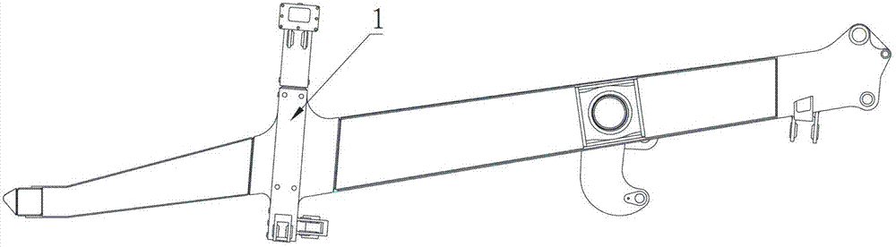
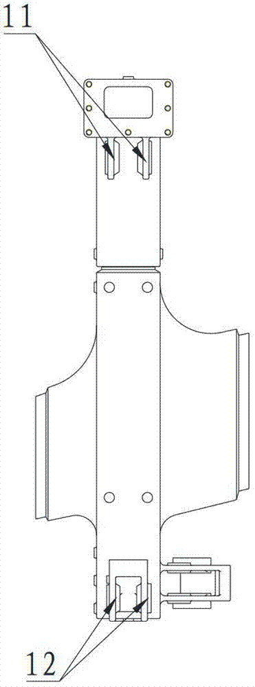
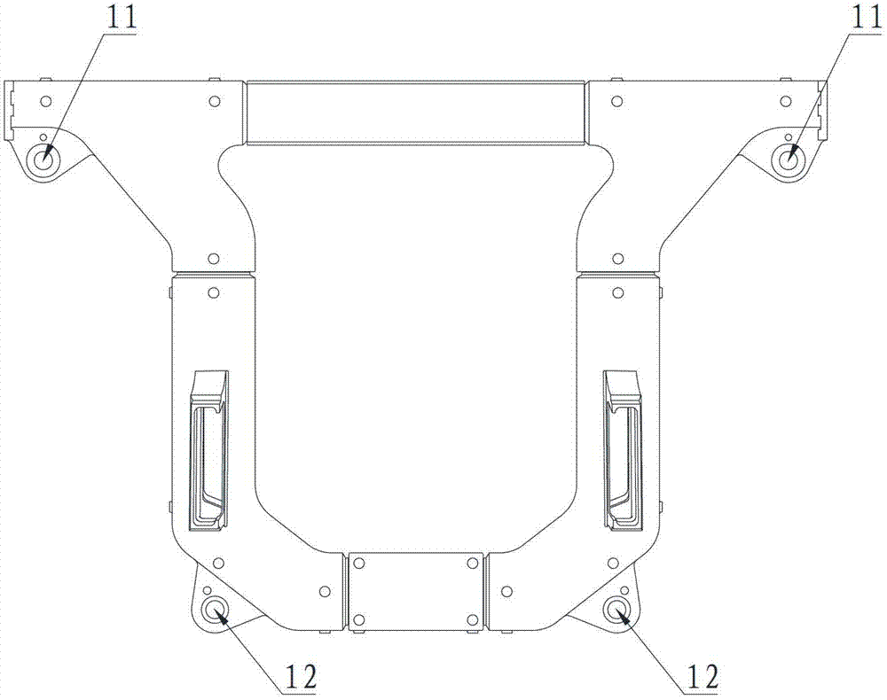
[0041] figure 1 , Figure 2A , Figure 2B It is a related drawing of the ring beam 1, as shown in the figure, the position of the ring beam 1 on the basic frame is inclined, and the whole ring beam 1 is a combined structure that is cast separately and welded together, only the The upper ear holes 11 on both sides of the upper end of the ring beam 1 and the lower ear holes 12 on both sides of the lower end have been finished and can be used as a positioning reference plane. The upper ear holes 11 and the lower ear holes 12 each include two lugs.

[0042] Figure 3A , 3B , 3C are respectively the front view, the left view and the top view of the ring beam 1 support of the present invention. ....


PUM


Abstract

The invention provides a ring beam support for adjusting position of a ring beam. The ring beam support comprises a fixed shaft, a swing base, a lifting table and a supporting base arranged sequentially from top to bottom. The fixed shaft is a shaft-shaped structure arranged on the ring beam in a penetrating manner and is arranged on the swing base. The swing base and the supporting base are of base-shaped structures and the lifting table is of a table-shaped structure. The swing base is connected on the lifting table moveably. The moveably connected rotary axis is arranged horizontally and vertical to the fixed shaft. A translating device which adjusts relative positions of the swing base and the lifting table along a direction of the rotary axis is arranged between the swing base and the lifting table. A lifting device which adjusts relative positions of the lifting table and the supporting base along a vertical direction is arranged between the lifting table and the supporting base. The ring beam support provided by the invention is simple in materials which are easy to obtain and simple in structure, and the whole ring beam support can be formed by a steel plate, a steel rod and a bolt. Therefore, the ring beam support provided by the invention is low in cost, convenient and reliable to operate and low in labor intensity.

Description

technical field [0001] The invention relates to the field of engineering machinery, in particular to a support for a ring beam of a vehicle frame. Background technique [0002] At present, the structural form of the basic frame of the mining rigid vehicle series is as follows: figure 1 Shown: From front to back, it is assembled and welded by bumper, front longitudinal beam, ring beam, rear longitudinal beam, torque tube and rear tailstock. Before welding, it is necessary to place the ring beam on the special tooling, adjust the ring beam up and down, left and right, and front and back, then insert the front longitudinal beam and rear longitudinal beam into the supports on the front and rear sides of the ring beam, and assemble the rest of the components. This form of assembly welding has the following operational difficulties: [0003] 1) The ring beam is a combined structure that adopts separate casting and welding together, with complex shape and large space size; [00...

Claims


Application Information

Patent Timeline
Patent Type & Authority Patents(China)
IPC IPC(8): B23K37/04
Inventor 高文德王双全邢一民
Owner SANY HEAVY EQUIP CO LTD
Why Eureka
Try Eureka