
Air-condition structure for ship

An air-conditioning and marine technology, applied in the field of marine air-conditioning structure, can solve the problems of time-consuming and laborious, troublesome and inefficient maintenance, and low production efficiency.

Active Publication Date: 2014-12-17
宁波沃弗圣龙环境技术有限公司
View PDF7 Cites 0 Cited by
  • Summary
  • Abstract
  • Description
  • Claims
  • Application Information

AI Technical Summary

Problems solved by technology

[0003] Due to the limited space on board, and the size of the marine air-conditioning structure itself is relatively large after it is fully assembled (the components that cause the large size are the three major components of the compressor, condenser and evaporator), if a marine air-conditioning structure has two or two For the above air-conditioning system, how to install the marine air-conditioning structure into the cabin is relatively difficult. Therefore, in order to solve the above problems, at present, the scattered parts are generally transported into the cabin, and the components are assembled in the cabin. After debugging, although the above method solves the problem that the structure of the marine air conditioner is difficult to enter the cabin, it is time-consuming and laborious, the production efficiency is low, and the assembly quality is difficult to control; in addition, in order to save space and improve production efficiency, the current customary design is to The evaporator, evaporator and compressor are stacked from bottom to top, that is, the condenser is used as a base to support the evaporator, and the evaporator supports the compressor. The condenser actually supports the evaporator and compressor at the same time. When the condenser or evaporator needs to be replaced, the compressor needs to be removed or the evaporator and compressor must be removed at the same time when the condenser is replaced, resulting in very troublesome and inefficient maintenance

Method used


Image

  • Air-condition structure for ship
  • Air-condition structure for ship
  • Air-condition structure for ship

Examples


Embodiment Construction

[0016] The present invention will be further described below in conjunction with accompanying drawing.

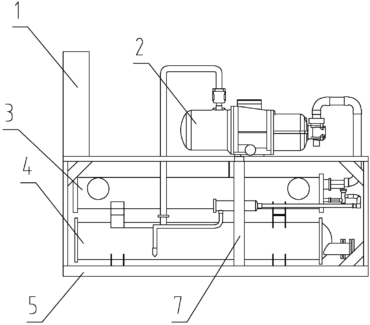
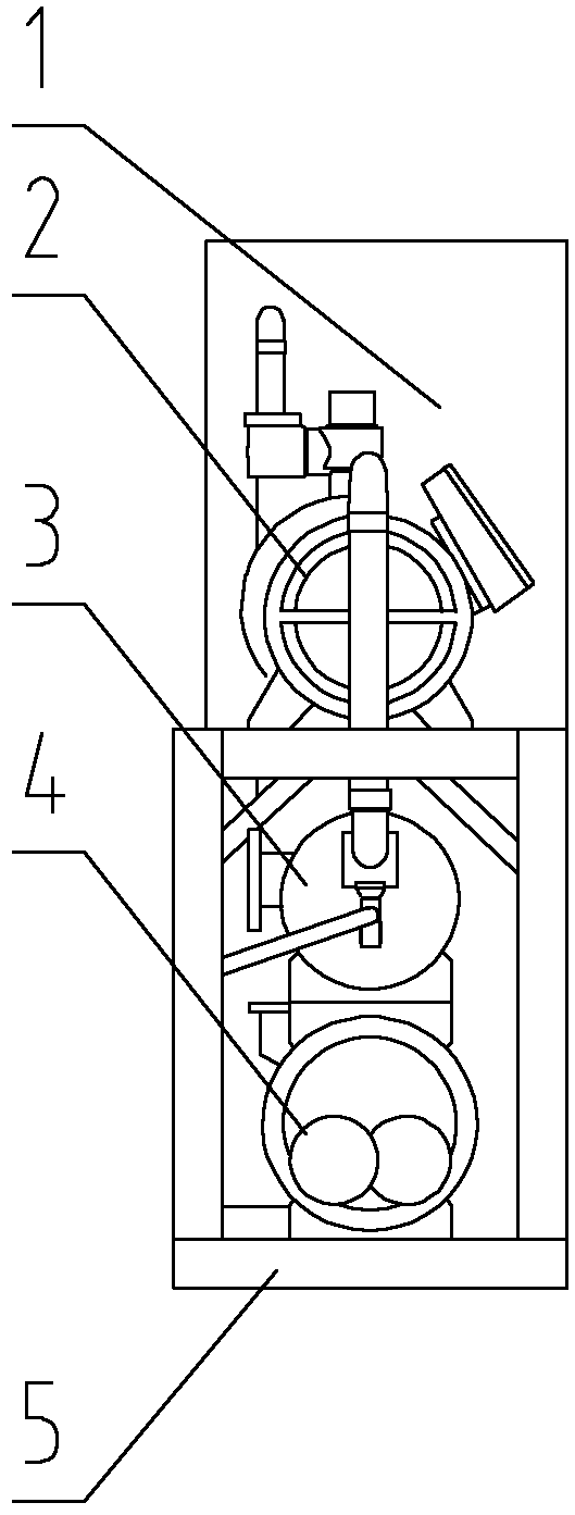
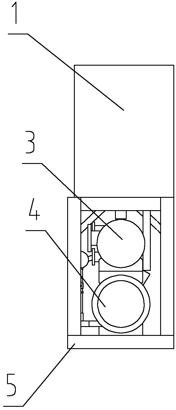
[0017] Marine air-conditioning structure of the present invention, it comprises at least one air-conditioning system, and this air-conditioning system comprises compressor 2, oil-gas separator, condenser 4, throttling valve and evaporator 3, and each air-conditioning system is provided with a supporting frame 5, compression The machine 2, the condenser 4 and the evaporator 3 are detachably connected with the frame 5; when there are two or more frames 5, adjacent frames 5 are detachably connected.

[0018] For each air conditioning system, the compressor 2, the evaporator 3 and the condenser 4 are distributed sequentially from top to bottom.

[0019] The part of the frame 5 below the compressor 2 is provided with reinforcing ribs 7 .

[0020] figure 1 , 2 , 3 illustrates the first embodiment, which has only one air conditioning system.

[0021] Figure 4 , 5 , 6 shows ...


PUM


Abstract

The invention discloses an efficient air-condition structure for a ship, which is convenient for entering into a cabin and is time-saving and labor-saving, high in production efficiency, easy in controlling assembling quality and simple in maintenance. The air-condition structure for the ship comprises at least one air-condition system, wherein the air-condition system comprises a compressor (2), an oil-gas separator, a condenser (4), a throttle valve and an evaporator (3); each air-condition system is provided with a frame (5) for supporting; the compressor (2), the condenser (4) and the evaporator (3) are detachably connected with the frame (5) respectively; and when two frames (5) or more frames exist, the adjacent frames (5) are detachably connected.

Description

technical field [0001] The invention relates to the technical field of fresh-keeping equipment, in particular to a marine air-conditioning structure. Background technique [0002] The existing marine air-conditioning structure includes at least one air-conditioning system, which mainly includes a compressor, an oil-gas separator, a condenser, a throttle valve and an evaporator. The working principle of the marine air-conditioning structure is that the water flow used for preservation Through the evaporator, the evaporator is used for cooling, so that the water circulates continuously, and the temperature of the water can be controlled within a certain range. [0003] Due to the limited space on board, and the size of the marine air-conditioning structure itself is relatively large after it is fully assembled (the components that cause the large size are the three major components of the compressor, condenser and evaporator), if a marine air-conditioning structure has two or ...

Claims


Application Information

Patent Timeline
Patent Type & Authority Patents(China)
IPC IPC(8): B63J2/02B63J2/12F24F1/02F24F13/32
Inventor 董云达
Owner 宁波沃弗圣龙环境技术有限公司
Learn More