Packaging device for backlight modules

A technology for backlight modules and holders, which is applied in transportation and packaging, packaging of vulnerable items, types of packaged items, etc. It can solve the problem of large fixation of the light guide plate, insufficient pressing force of the middle frame on the light guide plate, and affecting optical quality, etc. problem, to ensure the safety of transportation and prevent displacement

Active Publication Date: 2012-10-03
TCL CHINA STAR OPTOELECTRONICS TECH CO LTD
View PDF6 Cites 5 Cited by
  • Summary
  • Abstract
  • Description
  • Claims
  • Application Information

AI Technical Summary

Problems solved by technology

[0003] In the prior art, backlight modules are usually packaged in blister trays to achieve shockproof protection. Due to the limited strength of blister trays, it is not suitable for a large number of stacked up and down, otherwise it will easily affect the optical quality of the backlight module, so some people use The scheme of vertically placing the backlight module, but because the backlight module is a semi-finished product, the light guide plate and the optical film in the backlight module are not completely fixed, and the light guide plate is only fixed and limited by the middle frame
Due to the factors of assembly and parts tolerance, sometimes the pressing force of the middle frame on the light guide plate is insufficient, so that during the tra

Method used


Image

  • Packaging device for backlight modules
  • Packaging device for backlight modules
  • Packaging device for backlight modules

Examples


Example Embodiment

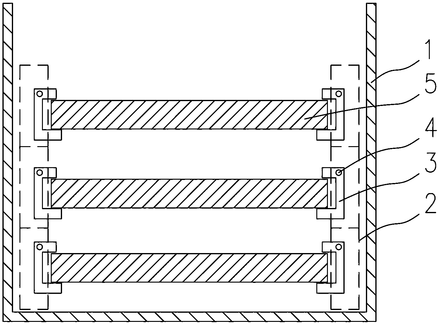
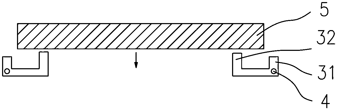
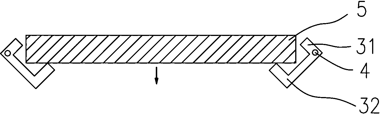
[0024] The invention discloses a packaging device for a backlight module, such as Figure 1 to Figure 5 As shown, it includes a fixed frame 2, a rotating shaft 4, and a retaining member 3 rotatable around the rotating shaft 4. The rotating shaft 4 is fixed on the fixed frame 2, and the retaining member 3 includes an upper arm 31 and a lower arm 32, The upper arm 31 and the lower arm 32 are used to hold the upper and lower surfaces of the backlight module 5 respectively.

[0025] In this embodiment, the packaging device further includes an outer box 1, the fixing frame 2 is placed in the outer box 1, the number of the fixing frame 2 and the clamping member 3 is four, divided into two rows, respectively used for clamping Two parallel sides of the backlight module 5. The upper arm 31 of the clamping member 3 is in a straight shape, the lower arm 32 is L-shaped, the upper arm 31 and the lower arm 32 form a C-shaped structure, and the rotating shaft 4 is arranged at the junction of t...


PUM


Abstract

The invention belongs to the field of crystal display, and particularly relates to a packaging device for backlight modules, which comprises a fixing bracket, a rotating shaft and a clamping part capable of rotating around the rotating shaft, wherein the rotating shaft is fixed on the fixing bracket; and the clamping part comprises an upper arm and a lower arm which are used for clamping the upper and the lower surfaces of each backlight module respectively. When the upper and the lower arms form an opening facing up, one edge of the backlight module can be placed above the lower arm, then the backlight module is lowered slowly, and the lower arm of the clamping part rotate around a fixed shaft; when the upper and the lower arms form an opening facing down, the lower arm is in contact with the lower surface of the backlight module to form a support state, and the upper arm of the clamping part is clung to the upper surface of the backlight module, so as to fix the backlight module completely. The packaging device can be stacked up and down, the stress on backlight modules on each layer is uniform, so as to solve the problem that the optical quality of the backlight modules is affected by gravity accumulation.

Description

technical field [0001] The invention belongs to the field of liquid crystal display, and more specifically relates to a packaging device for a backlight module. Background technique [0002] Existing liquid crystal display devices generally include components such as a front frame, a liquid crystal display panel, a middle frame, a light guide plate, and a back plate, and an optical film is attached to the light guide plate, wherein the front frame, the middle frame, and the back plate have different functions. The front frame is mainly used to fix the liquid crystal display panel and prevent it from jumping out, the back plate is mainly used to carry optical film, light guide plate, light bar and other components, and the middle frame is mainly used to fix the light guide plate and optical film together with the back plate And other optical components, while carrying the liquid crystal display panel, the backplane, the middle frame and the light guide plate, optical film and...

Claims


Application Information

Patent Timeline
IPC IPC(8): B65D81/05B65D85/30
CPCB65D81/05B65D85/48
Inventor 郭仪正陈仕祥俞刚周革革王甲强
Owner TCL CHINA STAR OPTOELECTRONICS TECH CO LTD
Why Eureka
Try Eureka