
Wire wheel unwinding frame

A technology of wire frame and wire wheel, which is applied in the field of power line winding equipment, can solve the problems of affecting production efficiency and winding quality reliability, difficult to control the winding force, and unable to wind the wire bag, etc., so as to save labor costs, The effect of simple structure and reliable performance

Inactive Publication Date: 2012-10-03
NANYANG POWER SUPPLY COMPANY OF STATE GRID HENAN ELECTRIC POWER
View PDF5 Cites 8 Cited by
  • Summary
  • Abstract
  • Description
  • Claims
  • Application Information

AI Technical Summary

Problems solved by technology

Due to the high pay-off speed, under the action of the rotation inertia of the wire wheel, when the winding speed of the wire package is uneven or stops, the wire wheel rotates according to its penetration speed, coupled with the lack of braking force, the winding package is not tight enough, not enough porcelain Reality
Therefore, two people are often required to cooperate, and one person is responsible for tensioning the wires, which not only takes time and effort, but also affects production efficiency and the reliability of winding quality.
In the invention patent 201110355299.9 published on April 4, 2012, a wire pay-off rack was proposed, which included wire reels, rollers, brackets, bases and brakes. For small wire reels and winding wire packages, the braking device is easy to cause the wire reel to shift, and it is difficult to control the winding force, and it is impossible to wind a uniform and solid wire package.

Method used


Image

  • Wire wheel unwinding frame

Examples


Embodiment Construction

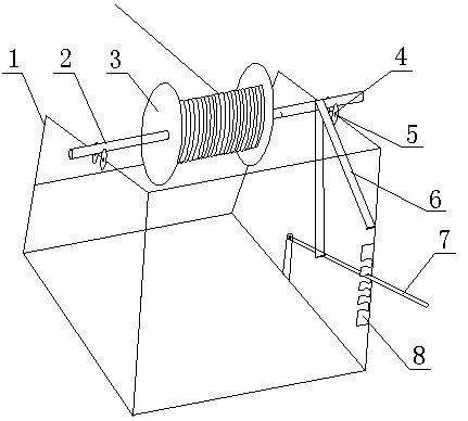
[0011] Such as figure 1 As shown, the reel pay-off frame of the present invention includes a bracket 1 and a rotating shaft 2 for threading the reel 3, and the rotating shaft 2 and the reel 3 should be closely matched to ensure that the two rotate synchronously. The top of the support 1 is provided with a support limit mechanism, which has 2 supporting rollers 4, the support rollers 4 are connected with the support 1 through the mandrel 5, and the support rollers 4 can rotate freely for supporting shaft 2, and prevent shaft 2 from moving radially. The lower part of the bracket 1 is provided with a tension brake device, which includes a positioning support plate 8, an operating rod 7 and a flexible friction belt 6, and the positioning support plate 8 is fixedly connected with the support 1, and the positioning One or more positioning slots are provided on the support plate 8 for the state positioning of the operating rod 7 during the tensioning operation. One end of the opera...


PUM


Abstract

The invention discloses a wire wheel unwinding frame. The frame comprises a bracket and a rotating shaft which penetrates through a wire wheel, wherein a support limit mechanism is arranged on the top of the bracket; a tensioning braking device is arranged on the lower part of the bracket; the support limit mechanism comprises support rollers which are connected with the bracket through mandrels; the tensioning braking device comprises a positioning support plate, an operating rod and a flexible friction belt; the positioning support plate is fixedly connected with the bracket and provided with a positioning clamping groove; one end of the operating rod is hinged with the bracket, and the other end of the operating rod is matched with the positioning clamping groove; and one end of the flexible friction belt is fixedly connected with the bracket, and the other end of the flexible friction belt moves around the rotating shaft and is connected with the operating rod. By the wire wheel unwinding frame, winding quality can be reliably ensured, and production efficiency is improved by more than two times; meanwhile, the occupancy rate of personnel can be reduced, labor intensity is reduced, and labor cost is saved; and the wire wheel unwinding frame has a simple structure, is convenient to operate, is simple, convenient and practical, and is reliable in performance.

Description

technical field [0001] The invention relates to the technical field of power line wrapping equipment, in particular to a wire wheel pay-off frame. Background technique [0002] At present, in the process of transformer manufacturing, maintenance and transformation, the wire reel and pay-off frame used for winding the wire package usually consists of two brackets and an iron rod. When paying off, the wire wheel rotates freely under the pull force of the winding end. Due to the high pay-off speed, under the action of the rotation inertia of the wire wheel, when the winding speed of the wire package is uneven or stops, the wire wheel rotates according to its penetration speed, coupled with the lack of braking force, the winding package is not tight enough, not enough porcelain Reality. Therefore, two people are often required to cooperate, and one person is responsible for tensioning and applying force to the wires, which not only takes time and effort, but also affects produ...

Claims


Application Information

Patent Timeline
Patent Type & Authority Applications(China)
IPC IPC(8): B65H49/30B65H59/38
Inventor 梁宪法赵林张征邓凤玲
Owner NANYANG POWER SUPPLY COMPANY OF STATE GRID HENAN ELECTRIC POWER
Learn More