Yarn closing mechanism of yarn guide system

A yarn guide and guide rod technology, applied in textile and papermaking, weft knitting, knitting and other directions, can solve the problems of slow yarn return of the yarn guide, unstable closing effect of the upper yarn, and yarn breakage, etc. The reciprocating speed of the machine head is improved, the structure is simple and sensitive, and the yarn guide tension is balanced.

Active Publication Date: 2014-04-23
CHANGSHU GUOGUANG MACHINERY
View PDF8 Cites 0 Cited by
  • Summary
  • Abstract
  • Description
  • Claims
  • Application Information

AI Technical Summary

Problems solved by technology

[0007] However, the types of wool yarns for knitting are often changed, and the number of strands and thickness of the raw materials are different. The above-mentioned clamping piece 300 cooperates with the spring 400. Since the spring 400 is fixed, it cannot be adjusted according to the type of yarn. , so this structure is not stable enough for the closing effect of the upper yarn, and the yarn guide (yarn feeder) returns slowly, which affects the quality of the fabric
[0008] In addition, during the weaving process, yarn disconnection often occurs. At this time, because there is no binding of the yarn guide to the thread take-up spring, the thread take-up spring of the thread take-up frame immediately bounces off. The yarn is very large, and the clamping piece 300 of the above structure cannot clamp the yarn, and the disconnected yarn end is sometimes difficult to find, causing the yarn to be disordered
The operator must integrate the yarn guiding steps when rejoining the yarn, which causes troubles when joining the yarn and increases the labor intensity of the operator
[0009] The patent application with the publication number of 102191624A discloses a yarn breaking and clamping device of a computerized flat knitting machine. Although it can prevent the yarn from escaping and facilitate the operator to grab and connect the yarn, its structure is too complicated, which increases the Production cost, and difficult to maintain

Method used


Image

  • Yarn closing mechanism of yarn guide system
  • Yarn closing mechanism of yarn guide system
  • Yarn closing mechanism of yarn guide system

Examples


Embodiment Construction

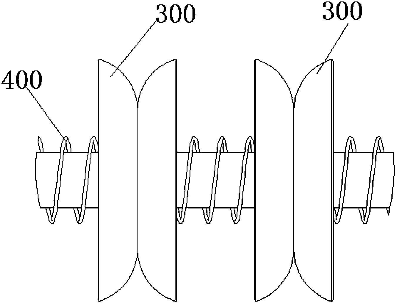
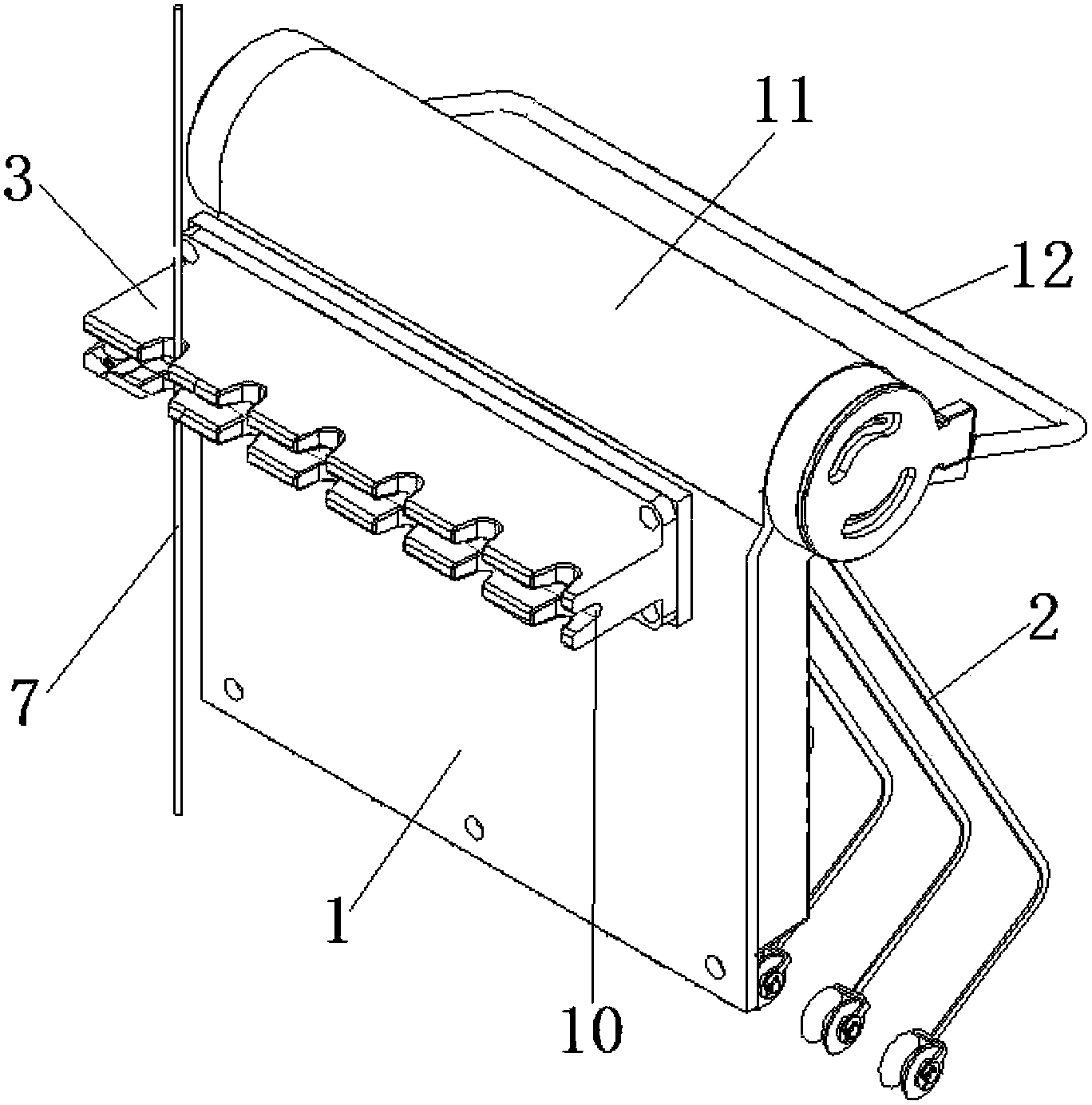
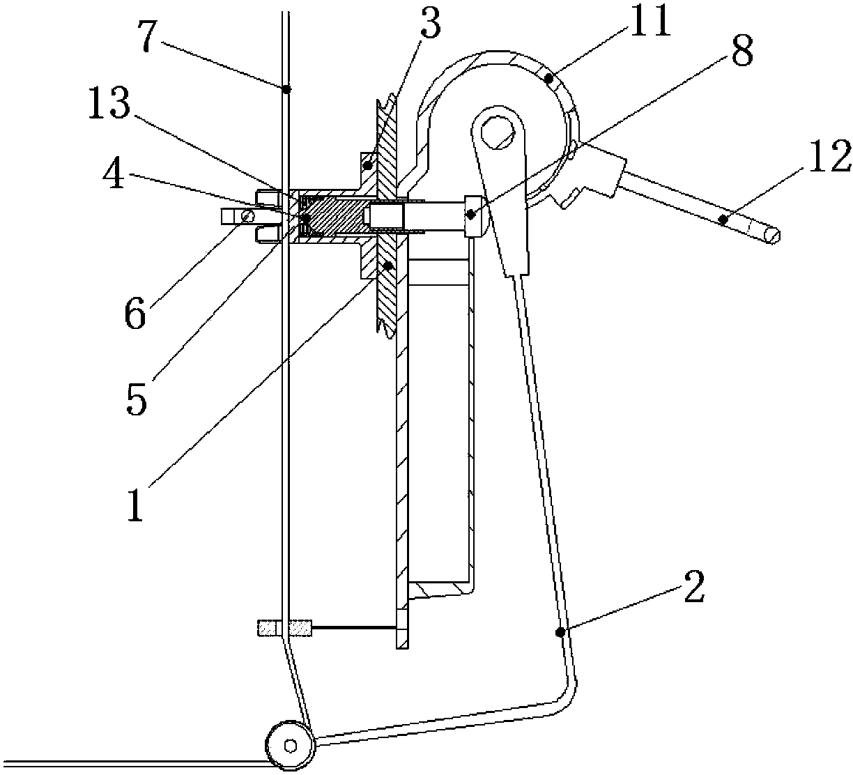
[0025] Such as figure 2 As shown, the yarn closing mechanism of the yarn guide system includes a thread take-up spring 2 installed on one side of the cover 1, and the other side of the cover 1 is provided with a yarn clamping seat 3, as image 3 , 4 As shown, a through hole is provided in the yarn clamping seat 3, and a guide rod 4 protruding from both ends of the through hole is provided in the through hole, and one end of the guide rod 4 crosses the cover 1 and rests on the root of the thread take-up spring 2 Next; the other end of the guide rod 4 protrudes through the through hole through the partition 5 arranged across the through hole, and is provided with a yarn clamping shaft 6 at its end, and the yarn 7 is arranged on the yarn clamping shaft 6 and the partition 5, through the movement of the guide rod 4 in the horizontal direction, the clamping shaft 6 is moved closer to the partition 5 to clamp the yarn 7, such as Figure 5 shown.

[0026] In order to adjust the a...


PUM


Abstract

The invention discloses a yarn closing mechanism of a yarn guide system, which includes a taking-up spring mounted on a protective cover; a yarn clamp base is arranged on the other side of the protective cover; a through hole is arranged in the yarn clamping base; a guide rod protruding out of two ends of the through hole is arranged in the through hole; one end of the guide rod transversely penetrates the protective cover and is propped against below the root part of the taking-up spring; the other end of the guide rod protrudes the through hole through transversely penetrating a partition arranged on the through hole; a yarn clamp axle is arranged at the end part of the guide rod; a yarn is arranged between the yarn clamp axle and the partition, and the yarn clamp axle is driven through horizontal movement of the guide rod to approach the partition so as to clamp the yarn; and an elastic device capable of enabling the guide rod to move towards the taking-up spring is arranged on the guide rod. The mechanism disclosed by the invention has small size as well as simple and ingenious structure, can accurately control clamping of the yarn, enables the yarn to be weaved under yarn guidance of balanced tension, improves the quality of braided fabric, has fast yarn guide speed, improves the reciprocating turnaround speed of the machine head, and achieves the effect that the machine head can turnaround rapidly to weave in a reciprocating manner.

Description

technical field [0001] The invention relates to a yarn closing mechanism of a yarn guiding system, which belongs to the technical field of computerized flat knitting machine manufacturing. Background technique [0002] In the knitting process of the computerized flat knitting machine, the yarn guide is an important link. There is a good yarn guiding process, corresponding to the yarn guiding process, there must also be a good yarn closing process. [0003] At present, whether it is a computerized flat knitting machine produced domestically or abroad, the yarn closing device in the wire mechanism mostly adopts such figure 1 The principle of the cooperation between the pair of clamping pieces 300 and the spring 400 shown is that the two clamping pieces 300 provide a certain resistance to the yarn under the action of the extrusion force generated by the elastic deformation of the springs 400 at both ends, so that they can be clamped. Hold the yarn. [0004] Since the clampin...

Claims


Application Information

Patent Timeline
Patent Type & Authority Patents(China)
IPC IPC(8): D04B15/56
Inventor 顾振刚顾文洁
Owner CHANGSHU GUOGUANG MACHINERY
Why Eureka
Try Eureka