

Compound vibrating type ice/snow removing shovel
A composite vibration, ice and snow technology, used in snow surface cleaning, cleaning methods, construction, etc., can solve problems such as limiting the scope of use of snow shovels
Inactive Publication Date: 2012-10-03
张铁民
View PDF9 Cites 6 Cited by
- Summary
- Abstract
- Description
- Claims
- Application Information
AI Technical Summary
Problems solved by technology
When the road surface is icy or the snow is compacted by vehicles, when the shovel blades of these ordinary mechanical snow shovels are pushed to slide forward along the road, the pressure on the ice and snow layer on the road surface due to the weight of the shovel body is less than the compressive strength of the ice and snow layer itself. , the shovel blade cannot cut off and penetrate the ice and snow layer to reach the road surface, the shovel blade will be cushioned by the ice layer or compacted snow layer on the road surface, and when sliding on the ice layer and compacted snow layer, it can only remove the floating debris on the upper surface of the ice layer. Snow, while hard ice and compacted snow cannot be stripped from the road surface, thus limiting the range of use of these snow shovels
Method used
View moreImage
Smart ImageViewing Examples

Examples
Embodiment Construction
Login to View More PUM
 Abstract
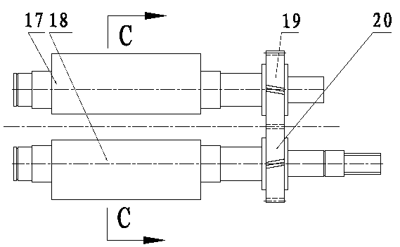
The invention relates to a compound vibrating type ice / snow removing shovel and especially relates to a snow shovel capable of generating a complex excitation force along vertical and horizontal directions. A vibrator is fixed on a shovel plate; an adjustable vertical excitation force is generated by the vibrator; a horizontal vibrating mechanism is arranged and is used for driving a horizontal eccentric vibrating shaft to rotate by a motor, so as to cause a shovel blade to reciprocate along the horizontal direction; a certain point on a road surface is repeatedly impacted by the shovel blade; and meanwhile the shovel blade has a certain impact force along the horizontal direction and has a certain function of removing ice and snow along the horizontal direction. The snow shovel mainly comprises the components, such as a shovel blade, a shovel plate, a rear turning obstacle avoidance mechanism, a four-connecting-rod combined mechanism, a vibrator, a horizontal vibrating shaft, a bias rotating shaft type road surface profiling mechanism, and the like. The snow shovel has the characteristics of removing the ice and snow under various states without damaging the road surface.
Description
technical field The invention relates to a composite vibrating snow removal shovel, which is mainly used for clearing snow on the road surface, and is especially suitable for clearing the compacted snow and ice layer that the ordinary mechanical snow removal shovel cannot do, and belongs to the field of road snow removal and deicing machinery . Background technique At present, ordinary mechanical snow shovels have been widely used in winter snow removal work. When these snow shovels clear the floating snow on the road surface, they rely on the gravity of the shovel body to form pressure on the ice and snow layer on the road surface, so that the shovel blade cuts off and penetrates the floating snow layer. On the road, the snow shovel is driven by the vehicle, and the shovel edge strips and pushes away the floating snow from the road to achieve the purpose of snow removal. When the road surface is icy or the snow is compacted by vehicles, when the shovel blades of these ordi...
Claims
Login to View More Application Information
Patent Timeline
 IPC IPC(8): E01H5/12
Inventor张铁民
Owner张铁民