
Printed circuit board drying device

A printed circuit board and drying device technology, which is applied in drying gas arrangement, progressive dryer, drying and other directions, can solve the problem of circuit board dehydration and poor drying effect, strong wind knife can not adjust the size of the air, drying device Complex structure and other problems, to achieve the effect of improving the baking quality

Inactive Publication Date: 2012-10-03
刘芝英
View PDF10 Cites 6 Cited by
  • Summary
  • Abstract
  • Description
  • Claims
  • Application Information

AI Technical Summary

Problems solved by technology

[0004] The existing traditional circuit board dryer is composed of a blowing device, a hot air device and a conveying device; Mainly use the blower to export the airflow in the machine through the strong wind knife, and realize the dehydration function of the circuit board under the action of the strong wind knife; The exported airflow is in the state of hot air, and the hot air is forced to dry the circuit board input on the conveying device through the action of the hot air knife; however, the existing printed circuit board drying device has a complicated structure, and the dehydration and drying effect of the circuit board is relatively low. Poor, and the strong wind wind knife can not adjust the size of the wind according to the actual situation, so it is difficult to meet people's use requirements

Method used


Image

  • Printed circuit board drying device
  • Printed circuit board drying device
  • Printed circuit board drying device

Examples


Embodiment Construction

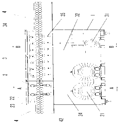
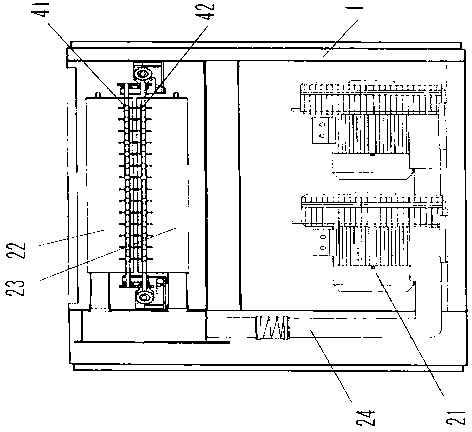
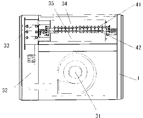
[0016] refer to figure 1 , figure 2 and image 3 As shown, a printed circuit board drying device includes a body 1, a blowing device 2, a hot air device 3 and a conveying device 4 are arranged in the body 1, and the conveying device 4 is an upper and a lower holder arranged on the body 1 Roller 41,42, the front end of conveying device 4 is provided with blowing device 2, and described blowing device 2 comprises air blower 21, and air blower 21 is connected with upper and lower strong wind wind knife 22,23 by air pipe 24, strong wind wind knife 22,23 The upper air outlet is located in the gap between the upper and lower rollers 41, 42. The rear end of the conveying device 4 is provided with a hot air device 3. The hot air device 3 includes a blower 31. The blower 31 passes through the air duct 32 and is heated. Device 33 is connected with upper and lower hot air air knives 34,35, and the air outlet on the hot air air knives 34,35 is positioned on the gap between upper an...


PUM


Abstract

The invention discloses a printed circuit board drying device which comprises a body, wherein the body is internally provided with an air blowing device, a hot air device and a conveying device, wherein the conveying device is an upper carrier roller and a lower carrier roller which are arranged on the body; the front end of the conveying device is provided with the air blowing device; the air blowing device comprises an air blower; the air blower is connected with an upper air intensifying air knife and a lower air intensifying air knife through air pipes; air outlets on the air intensifying air knives are positioned on a clearance between the upper carrier roller and the lower carrier roller; the rear end of the conveying device is provided with the hot air device; the hot air device comprises an air blower; the air blower is connected with an upper hot air knife and a lower hot air knife by air pipes through a heater; and air outlets on the hot air knives are positioned on the clearance between the upper carrier roller and the lower carrier roller. The effective design enables residual solvents attached to a circuit board to be volatilized rapidly, and the braking quality of the printed circuit board is improved greatly.

Description

technical field [0001] The invention relates to a drying machine, in particular to a drying device for printed circuit boards. [0002] Background technique [0003] The printed circuit board is to print the required circuit layout on the multi-layer board body, and then compound the multi-layer board to form a circuit board body, and then the board surface must be coated with a layer of ink containing solvent, and placed Dry in a special dryer to volatilize the solvent in the ink layer on the board to achieve the purpose of drying. [0004] The existing traditional circuit board dryer is composed of a blowing device, a hot air device and a conveying device; Mainly use the blower to export the airflow in the machine through the strong wind knife, and realize the dehydration function of the circuit board under the action of the strong wind knife; The exported airflow is in the state of hot air, and the hot air is forced to dry the circuit board input on the conveying d...

Claims


Application Information

Patent Timeline
Patent Type & Authority Applications(China)
IPC IPC(8): F26B15/12F26B21/00
Inventor 不公告发明人
Owner 刘芝英
Learn More