Two-dimensional visualized test device of work mechanism of anchoring system

A test device and anchoring system technology, applied in measuring devices, instruments, scientific instruments, etc., can solve the problems of difficulty in accurate monitoring, small contact area, and the uniformity of force on the sample, so as to ensure stability, reasonable structure, The effect of easy disassembly

Inactive Publication Date: 2014-01-29
INST OF ROCK & SOIL MECHANICS CHINESE ACAD OF SCI
View PDF4 Cites 0 Cited by
  • Summary
  • Abstract
  • Description
  • Claims
  • Application Information

AI Technical Summary

Problems solved by technology

At this time, the anchor rod is installed in the borehole and is in a closed state. It is impossible to directly observe the development process of the anchoring agent and the deformation and cracking of the anchoring body during the drawing process, as well as the deformation process of the anchor rod. The interface between the anchoring agent and the anchoring agent and the anchoring body is a circular arc surface, and the contact area is very small, so it is very difficult to accurately monitor. Therefore, the understanding of the mechanical behavior of the two interfaces and the mathematical and mechanical description have always been a key problem in this field.
In addition, although the sample chamber of the traditional test device is also composed of a loading plate and a fixed plate, in order to avoid that the load cannot be transmitted to the side of the sample after the steel plates are in contact, the length and width of the steel plate are usually smaller than the length and width of the side of the sample. In this way, there must be blanks at the eight corners, which will affect the uniformity of the force on the sample.

Method used


Image

  • Two-dimensional visualized test device of work mechanism of anchoring system
  • Two-dimensional visualized test device of work mechanism of anchoring system

Examples


Embodiment Construction

[0010] The following is a further detailed description of the two-dimensional visualization test device for the working mechanism of the anchoring system of the present invention in conjunction with the accompanying drawings.

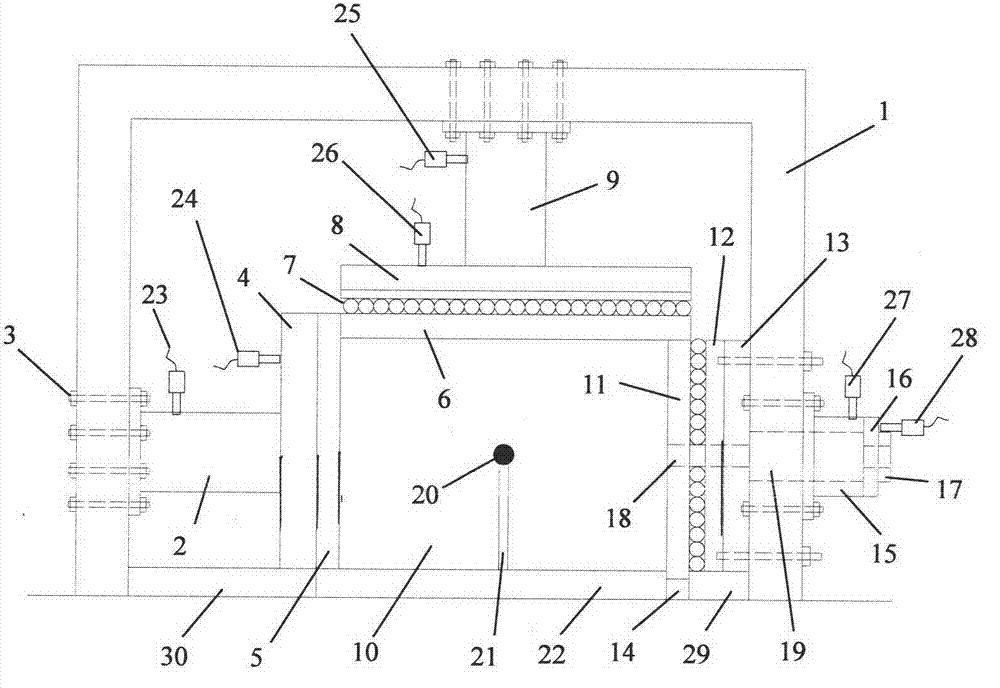
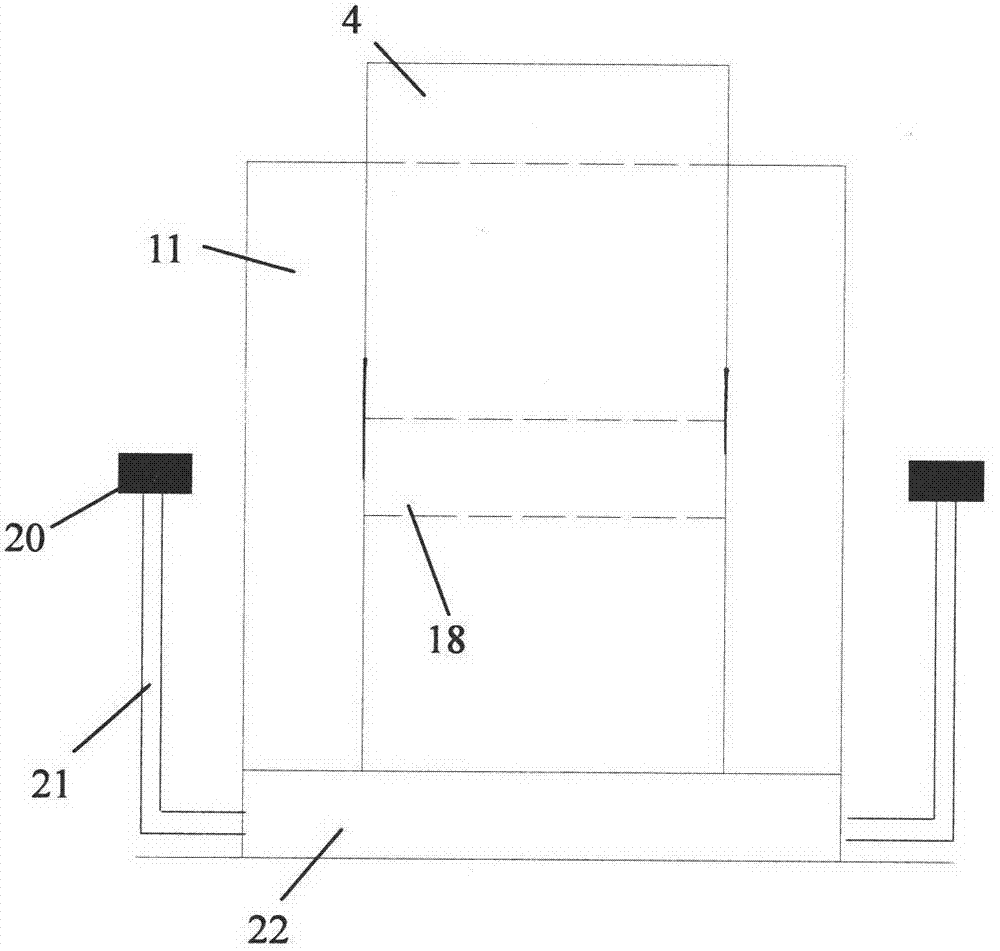
[0011] Referring to the accompanying drawings, the two-dimensional visualization test device of the present invention is composed of a sample chamber 10, a horizontal loading system, a vertical loading system, a horizontal fixing system, an anchor rod pulling system and a monitoring system.

[0012] The sample chamber 10 has a frame structure and is composed of a left loading plate 5, a top loading plate 6, a right fixing plate 11, a bottom plate 22 and a corner plate 14. The bottom plate 22 is placed horizontally, and the left loading plate 5 and the right fixing plate 11 are parallel to each other, the left loading plate 5 is vertically placed above one end of the bottom plate 22, the corner plate 14 is positioned on the other side wall of the bottom p...


PUM


Abstract

The invention relates to a two-dimensional visualized test device of the work mechanism of an anchoring system, belonging to the technical field of geotechnical engineering. The two-dimensional visualized test device is formed by combining a left-side loading plate (5), a top loading plate (6), a right-side fixed plate (11), a bottom plate (22), a camera device (20), and the like. According to the two-dimensional visualized test device, a sample chamber (10) of is formed by adopting a staggered plate method, and therefore, the problem of blank corner of an anchoring body is solved; the camera device (20) is arranged so as to shoot the behavioral process of forming the anchoring system by an anchor rod, an anchoring agent and the anchoring body in the overall drawing process of the anchor rod in a whole course, and the behavioral process can be directly observed by eyes, and therefore, the limitation of inconvenient monitoring and observation of the mechanical response of the anchoring system in the traditional three-dimensional test is overcome; and the test basis of the research of the work mechanism of the anchoring system is provided. The invention can be widely used for the test research of a full-length bond-type anchor rod and the mechanical behavior and the work mechanism of the corresponding anchoring system in geotechnical engineering.

Description

Technical field: [0001] The invention relates to a two-dimensional visualization test device for the working mechanism of an anchoring system, which belongs to the technical field of geotechnical engineering. The device can be used in the experimental research on the mechanical behavior and working mechanism of full-length bonded anchor rods and corresponding anchoring systems in geotechnical engineering . Background technique: [0002] Bolt is the most widely used method of support and reinforcement in geotechnical engineering, and full-length bonded bolt is the most widely used type of bolt. The reinforced rock and soil mass is called an anchor, and the anchor rod and the anchor are bonded together by an anchoring agent or a binder. Although this type of anchor is widely used, revealing the working mechanism of the corresponding anchoring system has always been a research problem in this field. The anchor pullout test is the main test method in the study of this problem,...

Claims


Application Information

Patent Timeline
Patent Type & Authority Patents(China)
IPC IPC(8): G01N3/00
Inventor 张传庆周辉徐荣超杨凡杰卢景景
Owner INST OF ROCK & SOIL MECHANICS CHINESE ACAD OF SCI
Why Eureka
Try Eureka