On-load continuous transformer

A transformer and font technology, applied in transformers, variable transformers, variable inductors, etc., can solve problems such as contact arcs and achieve the effect of eliminating arcs

Inactive Publication Date: 2012-10-03
吴江市东泰电力特种开关有限公司
View PDF5 Cites 4 Cited by
  • Summary
  • Abstract
  • Description
  • Claims
  • Application Information

AI Technical Summary

Problems solved by technology

[0004] The current on-load tap-changer mainly realizes the tapping of each contact through the transition circuit. Even so, there is still a potential difference between the contact points of each switch. In the case of humidity or a large voltage adjustment range, due to the There is still a potential difference between the contacts, so arcing can still occur between the contacts when the voltage is switched

Method used


Image

  • On-load continuous transformer
  • On-load continuous transformer
  • On-load continuous transformer

Examples


Embodiment Construction

[0016] Below in conjunction with accompanying drawing and embodiment the present invention is further described:

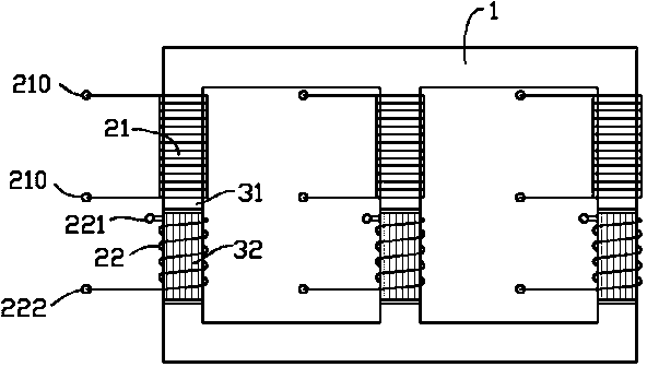
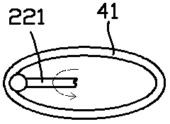
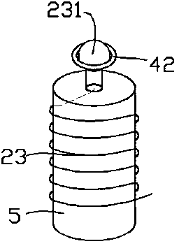
[0017] exist figure 1 — image 3 In the shown embodiment, the on-load continuous transformer includes a Japanese-shaped iron core 1, and primary coils 21 and secondary coils 22 wound on three parallel horizontal columns of the Japanese-shaped iron core 1; The horizontal column is composed of two sections, one of which is a fixed column 31 wound with the primary coil 21, the two terminals 210 of the primary coil are connected to the input voltage, and the other section is a freely rotatable rotating column 32 wound with a The secondary coil 22, one end of the secondary coil 22 is electrically connected to a brush head 221 fixed on the rotating column 32, and the brush head 221 is output through the conductive ring 41, as figure 2 As shown, in actual wiring, the conductive rings 41 corresponding to the secondary coils 22 are electrically connected as a common zer...


PUM


Abstract

The invention provides an on-load continuous transformer which comprises a B-shaped iron core, a primary winding and a secondary winding. The primary winding and the secondary winding are wound on three parallel cross columns of the B-shaped iron core. Each cross column consists of two sections, one section is a fixed column wound with the primary winding, and the other section is a freely-rotatable rotary column wound with the secondary winding. One end of the secondary winding is electrically connected with an electric brush fixed on the rotary column. The electric brush outputs through a conductive ring. The other end of the secondary winding extends to a rotatable winding column driven by a motor and is wound on the same and electrically connected with an electric brush fixed on the winding column. The electric brush of the winding column also outputs through a conductive ring. Without a tap switch, the on-load continuous transformer can realize continuous adjustment of the transformer ratio and completely suppress generation of electric arcs.

Description

technical field [0001] The invention relates to the field of electric basic equipment, in particular to a power transformer, which includes an iron core, a primary coil and a secondary coil. Background technique [0002] In the field of civil power supply, high-voltage power is usually used for power transmission, which can reduce the loss of current on the transmission line. Near the user end, it is usually necessary to set up a substation to step down the high-voltage power to meet the normal power consumption requirements. Mains voltage, namely 220V. [0003] Under normal circumstances, the power consumption at the user end varies greatly between the peak and the low peak. Due to the line loss, when the power consumption fluctuates, the actual voltage at the user end will also change. In this way, the transformer needs to continuously adjust the transformation voltage. Ratio, in order to stabilize the actual voltage at the user end, this process is achieved by changing ...

Claims


Application Information

Patent Timeline
Patent Type & Authority Applications(China)
IPC IPC(8): H01F29/04H01F29/06
Inventor 李紫薇
Owner 吴江市东泰电力特种开关有限公司
Why Eureka
Try Eureka