Traction reposition frame

A technology of traction reset and traction components, which is applied in the field of traction reset frames, and can solve problems such as inability to achieve changes

Inactive Publication Date: 2014-05-14
安徽埃克索医疗机器人有限公司
View PDF5 Cites 2 Cited by
  • Summary
  • Abstract
  • Description
  • Claims
  • Application Information

AI Technical Summary

Problems solved by technology

This invention also fails to change the angle of the patient's calf axis relative to the thigh axis and the angle of the thigh axis relative to the bed surface

Method used


Image

  • Traction reposition frame
  • Traction reposition frame
  • Traction reposition frame

Examples


Embodiment Construction

[0026] The present invention is described below in conjunction with accompanying drawing.

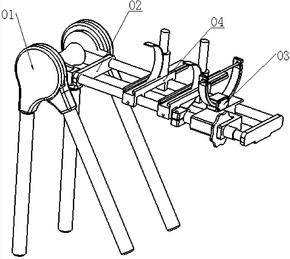
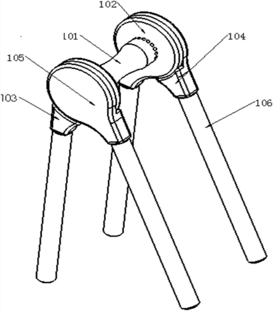
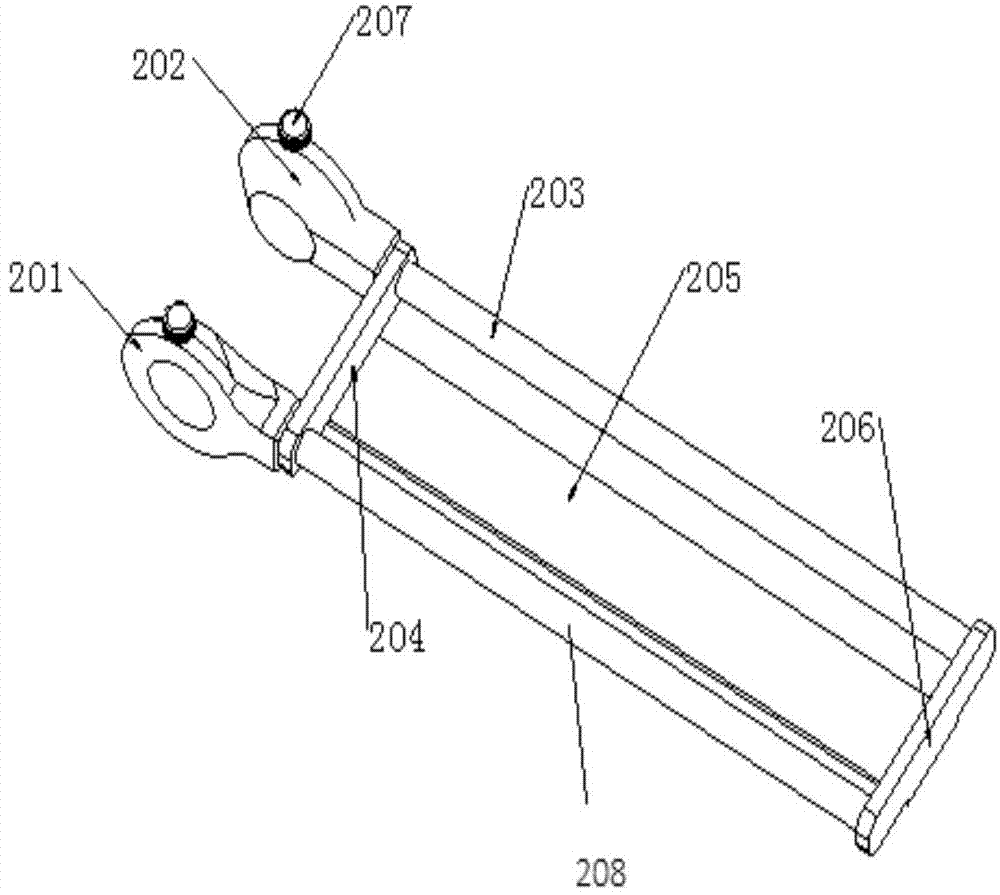
[0027] refer to figure 1 , shows a perspective view of an embodiment of the traction reset frame according to the present invention. The traction reset frame of the present invention includes: a height-adjustable bracket assembly 1 with a leg rest 101; a swing frame assembly 2 pivotally connected to the leg rest 101, and a slidable traction assembly 3 is arranged on the swing frame assembly 2, wherein, The bracket assembly 1 and the traction assembly 3 are operatively locked or unlocked with the pendulum assembly 2 respectively. When in use, the patient's calf is placed on the pendulum assembly 2, and the inner side of the patient's knee joint is supported by the leg pillow 101, so that a certain angle is formed between the thigh and the bed surface, and the height of the support is adjustable, so that the thigh The angle formed with the bed surface is adjustable. The swing frame ass...


PUM


Abstract

The invention provides a traction reposition frame. The traction reposition frame comprises a support assembly (1) with the height adjustable and a swing frame assembly (2), wherein the support assembly (1) is provided with a leg pillow (101), the swing frame assembly (2) is connected with the leg pillow (101) in a pivot mode and provided with a sliable traction assembly (3), the support assembly (1) and the swing frame assembly (2) are locked or unlocked in an operable mode, and the traction assembly (3) and the swing frame assembly (2) are locked or unlocked in an operable mode. The traction reposition frame can adjust the angle between the axis of one thigh of a patient and the bed surface and the angle between the axis of one crus and the axis of the corresponding thigh to provide convenience for operations.

Description

technical field [0001] The invention relates to a traction reduction frame used for calf fracture operation. Background technique [0002] The traction and reduction operation of calf fracture is the key link in the treatment of calf fracture. Its content is to apply force in opposite directions at both ends of the fracture site to pull the fractured bone apart, and then align the fractured bone according to the anatomical structure of the calf bone, and recover. to a healthy position. [0003] In the traditional calf fracture treatment operation, the traction reduction operation is completed by the doctor's free hand traction, or by the traction device of the orthopedic traction table. Manual stretching and reset operation, the doctor can easily complete the traction reset operation according to his own experience and X-ray pictures. However, after the traction position is restored, it is necessary to remain in the correct position for other surgical operations such as in...

Claims


Application Information

Patent Timeline
Patent Type & Authority Applications(China)
IPC IPC(8): A61F5/045
Inventor 唐佩福王田苗张立海胡磊
Owner 安徽埃克索医疗机器人有限公司
Why Eureka
Try Eureka