Electrical connector with separation power-assisting mechanism and assembly thereof

A technology for electrical connectors and power assist mechanisms, which is applied to the parts, connections, and electrical components of connecting devices, and can solve problems such as difficulty in separating electrical connectors.

Inactive Publication Date: 2012-10-03
CHINA AVIATION OPTICAL-ELECTRICAL TECH CO LTD
View PDF4 Cites 2 Cited by
  • Summary
  • Abstract
  • Description
  • Claims
  • Application Information

AI Technical Summary

Problems solved by technology

[0003] The object of the present invention is to provide an electrical connector with a separation power-assisted mechanism to solve the problem of difficulty in separating the electrical connector under the premise of ensuring that the plug and socket of the electrical connector can be locked

Method used


Image

  • Electrical connector with separation power-assisting mechanism and assembly thereof
  • Electrical connector with separation power-assisting mechanism and assembly thereof
  • Electrical connector with separation power-assisting mechanism and assembly thereof

Examples


Embodiment Construction

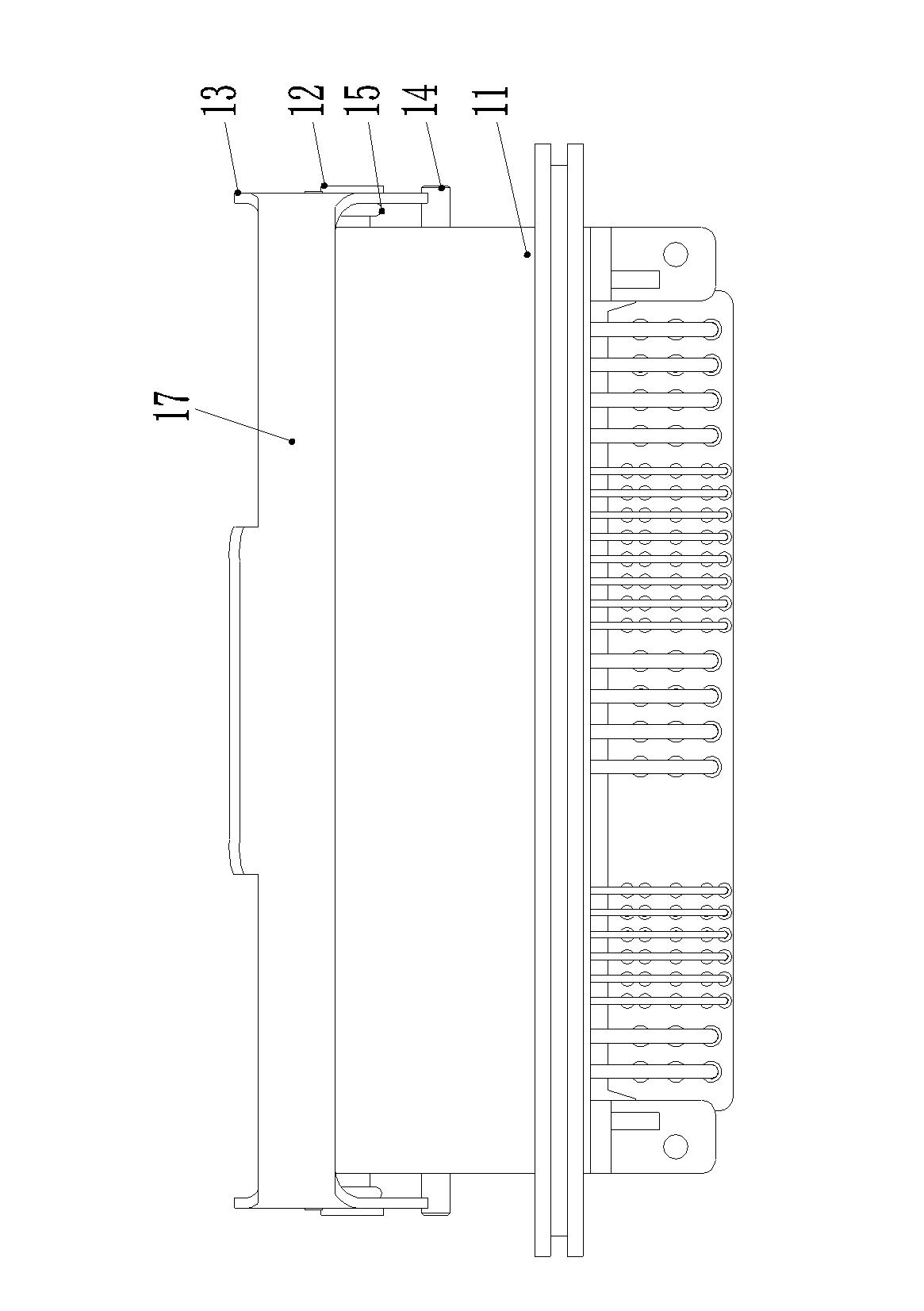
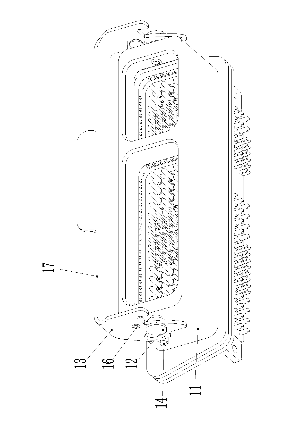
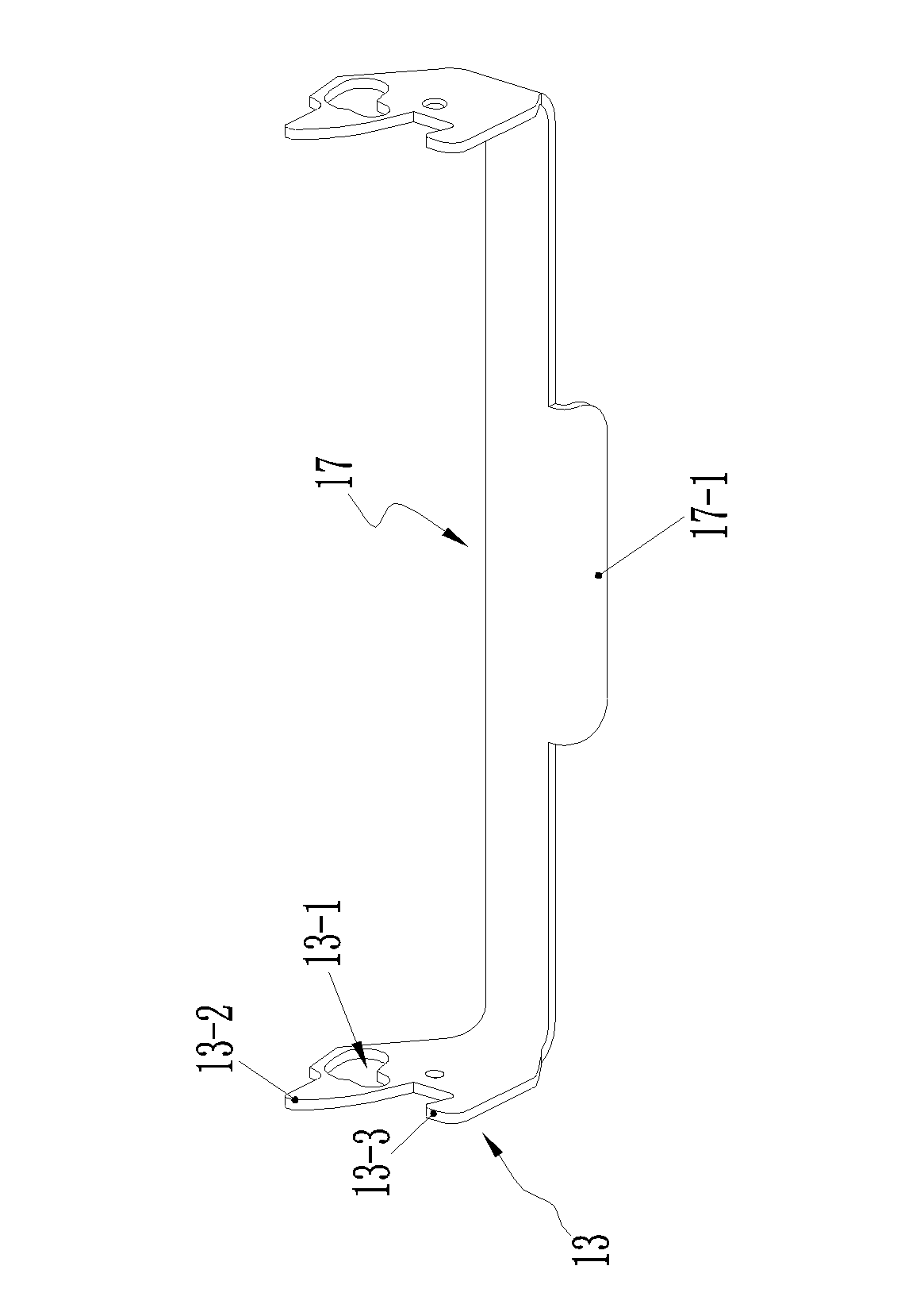
[0032] Embodiment 1 of the electrical connector with separation assist mechanism of the present invention, such as Figure 1-7As shown, the electrical connector in this embodiment is a rectangular electrical connector. The electrical connector includes a housing 11. The housing 11 is a metal housing with the front end as the insertion end. The front end of the housing 11 is on the left and right Both sides are equipped with pins 12 and lock plates 13 through the pins 12 respectively. The axes of the pins 12 extend along the left and right directions and are blocked and matched with the corresponding lock plates through their nail caps, so that the lock plate 13 and the housing 11 The lock plate 13 is fitted with a pin through a track hole 13-1 provided on it, and the rear end of the lock plate 13 can swing in the front and rear direction, which makes the lock plate 13 on the housing It has a locking station and an unlocking station. In addition, the front end of the lock plate...


PUM


Abstract

The invention relates to an electrical connector with a separation power-assisting mechanism and an assembly thereof. The front end of the electrical connector is used as a plugging end; the electrical connector comprises a shell; both left and right sides of the front end of the shell are respectively provided with lock plates capable of swinging along the back-and-forth direction of the shell by dowels in an anti-falling mode; the lock plates are provided with locking stations and unlocking stations on the shell; spring locking mechanisms are arranged between the shell and the lock plates; the front end of each lock plate is provided with a hook part for being hooked and matched with an adaptive connector when the lock plate is positioned in the locking state and a prying arm part for prying the adaptive connector forward when or after the lock plate is separated from the adaptive connector in the process of swinging backward to the unlocking station from the locking station; supporting mechanisms for providing fulcrums for the corresponding lock plates when the corresponding prying arm parts work so as to ensure the lock plates to be formed into level mechanisms is arranged behind the dowels on the shell; and track holes for compensating the relative displacement between the corresponding lock plates and the corresponding dowels when the lock plates reciprocate between the locking stations and the unlocking stations are arranged on the lock plates. The problem of difficulty in separating the electrical connector is solved.

Description

technical field [0001] The invention relates to the field of electrical connectors, in particular to an electrical connector with a separation booster mechanism and components thereof. Background technique [0002] With the rapid development of integration and modularization of electrical equipment, the application of electrical connector components is becoming more and more extensive. In some special occasions, it is required that the plug and socket of the electrical It is extremely difficult to separate from the socket, that is, the pulling force between the two is large, which brings inconvenience to the operation of the staff; in addition, when the number of contacts on the electrical connector is large, it will also cause the electrical connector assembly. The increase of the bonding force between the plug and the socket; however, even so, the bonding force between the plug and the socket still cannot meet the requirements of the working environment in some occasions. ...

Claims


Application Information

Patent Timeline
Patent Type & Authority Applications(China)
IPC IPC(8): H01R13/629H01R13/639H01R24/00
Inventor 杨德广
Owner CHINA AVIATION OPTICAL-ELECTRICAL TECH CO LTD
Why Eureka
Try Eureka