

Rack traveling type coil conveying device
A coil handling device and mobile technology, applied in rack railway, transportation and packaging, motor vehicles, etc., can solve problems such as the bad influence of the movement of the handling trolley, and achieve the effect of high-speed and stable handling
- Summary
- Abstract
- Description
- Claims
- Application Information
AI Technical Summary
Problems solved by technology
Method used
Image

Examples
Embodiment 1
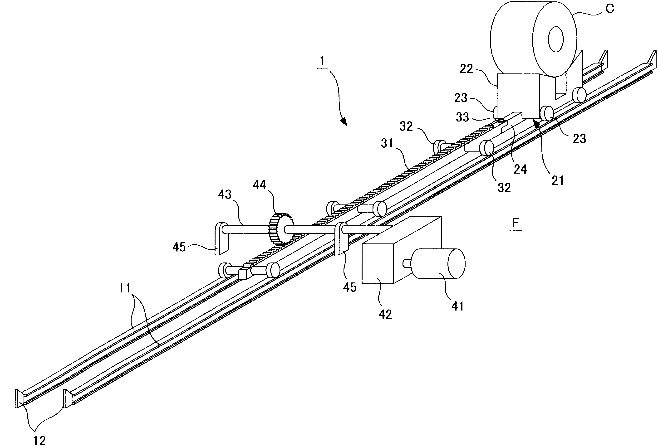
[0047] First, use figure 1 , the rack moving type coil conveying device 1 will be described in detail.
[0048] Such as figure 1 As shown, the coil conveyance device 1 includes a pair of left and right rails 11 provided on a floor surface (fixed portion) F, and a coil conveyance trolley 21 movable on the rails 11 .
[0049] The pair of left and right rails 11 are formed in a linear shape, and stoppers 12 for wheel stoppers are provided at both ends thereof.
[0050] The coil transport trolley 21 includes: a pallet part 22; a pair of left and right trolley moving wheels 23 supported rotatably by the side of the pallet part 22; . The pallet part 22 can load the coil C which coiled the rolled material (not shown) in coil shape, and can hold this coil C so that the axial center may become horizontal. Furthermore, the trolley moving wheels 23 roll on the rail 11 and contact the stopper 12 of the rail 11 to prevent detachment from the rail 11 .
[0051] In addition, one end of ...
Embodiment 2
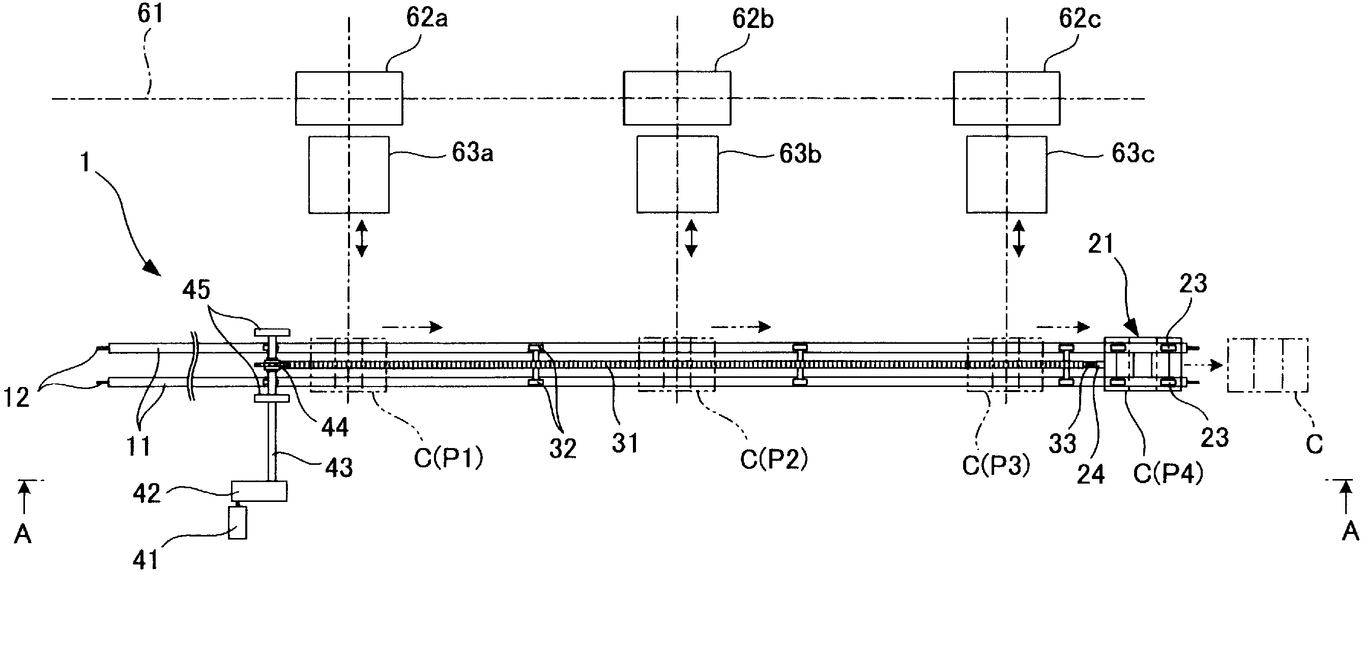
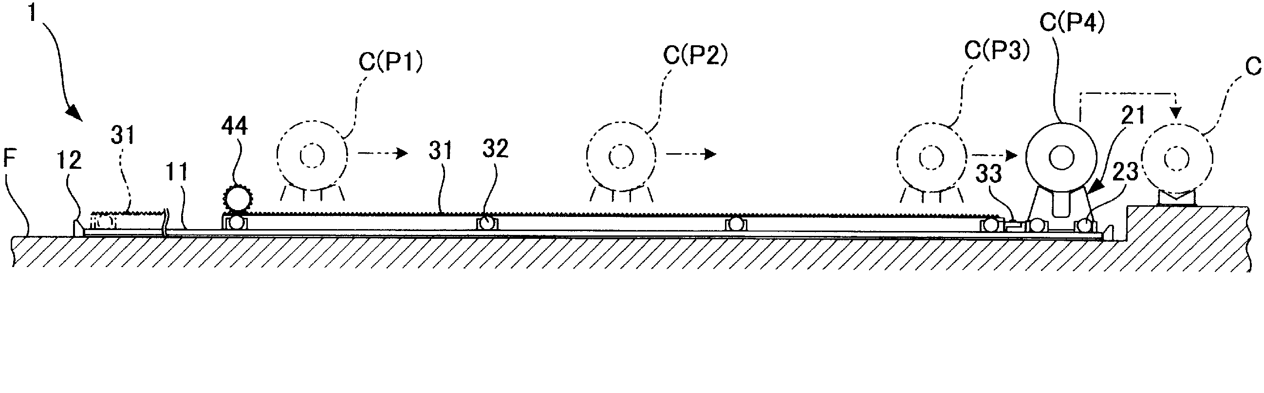
[0073] Next, use Figure 4 and Figure 5 , detailing the application of the coil conveying device 1 between the rolling workshop workshop and the coil yard workshop.
[0074] Such as Figure 4 and Figure 5 As shown, a rolling workshop 71 of the above-mentioned hot rolling line 61 and a coil yard workshop 72 arranged separately from the rolling workshop 71 are provided in the ironworks area. In addition, between the rolling workshop workshop 71 and the coil yard workshop 72, an upper and lower two-stage coil conveying device 1 is provided. That is, in order to transfer the coil C coiled by the down coilers 62a, 62b, and 62c of the hot rolling line 61 from the rolling workshop 71 of the hot rolling line 61 to the coil yard 72, two upper and lower stages are provided. The coil handling device 1.
[0075] It should be noted that the same reference numerals are assigned to the same components as those described in the first embodiment, and redundant descriptions will be omitt...
Embodiment 3
[0089] Next, use Figure 6 to Figure 9 , to describe in detail the application of the coil handling device 1 in the workshop of the coil yard. It should be noted that the same components as those described in the first and second embodiments are given the same reference numerals, and repeated descriptions are omitted.
[0090] Such as Figure 6 As shown, in the above-mentioned coil yard workshop 72, a trolley circulation type coil conveyance facility 80 for conveying the loaded coil C to the coil yard (not shown) is provided. The trolley circulation type coil handling equipment 80 includes a coil intermittent handling device (a trolley group intermittent moving mechanism, a coil intermittent handling mechanism) 81, an empty trolley pulling device (a first moving mechanism, a trolley pulling mechanism) 82. Empty trolley extruding device (second moving mechanism, trolley extruding mechanism) 83. Coil conveying device 1 (hereinafter, It is called empty trolley handling device ...
PUM
 Abstract
Description
Claims
Application Information