Illumination device

A lighting device and cooling body technology, which is applied in the direction of lighting devices, lighting device components, lighting device cooling/heating devices, etc., to achieve the effect of large surface, cheap price, and improved proximity

Inactive Publication Date: 2012-10-03
OSRAM GMBH
View PDF5 Cites 6 Cited by
  • Summary
  • Abstract
  • Description
  • Claims
  • Application Information

AI Technical Summary

Problems solved by technology

In order to replace conventional incandescent bulbs by LED lamps (LED-incandescent retrofit lamps), in this case the following problems arise for the replacement of conventional incandescent bulbs by LED lamps (LED-incandescent retrofit lamps): Typica

Method used


Image

  • Illumination device
  • Illumination device
  • Illumination device

Examples


Embodiment Construction

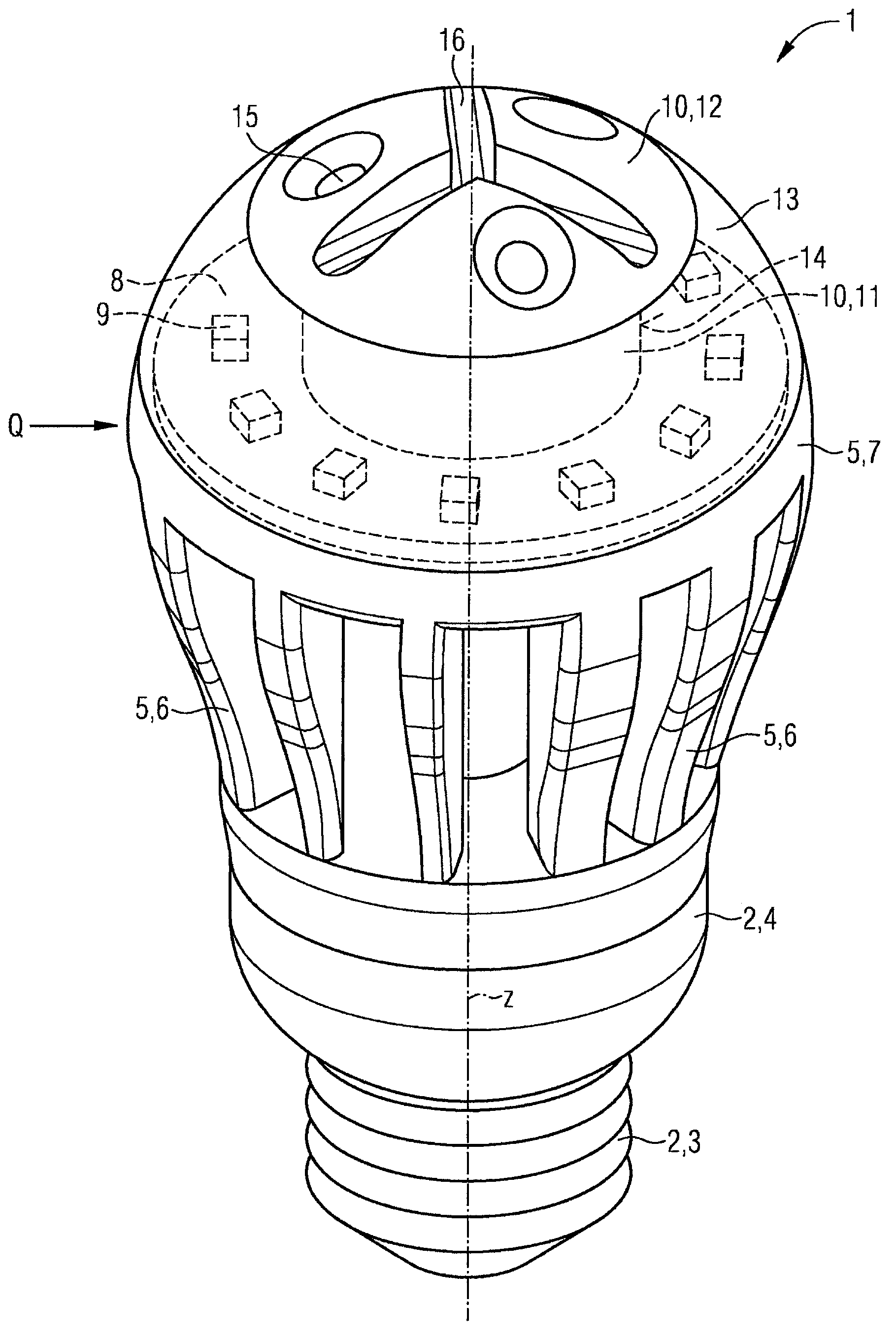
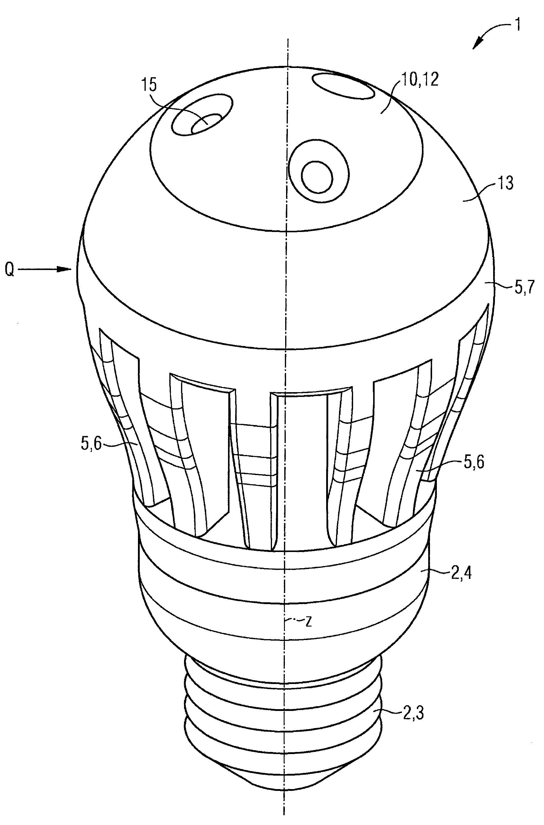
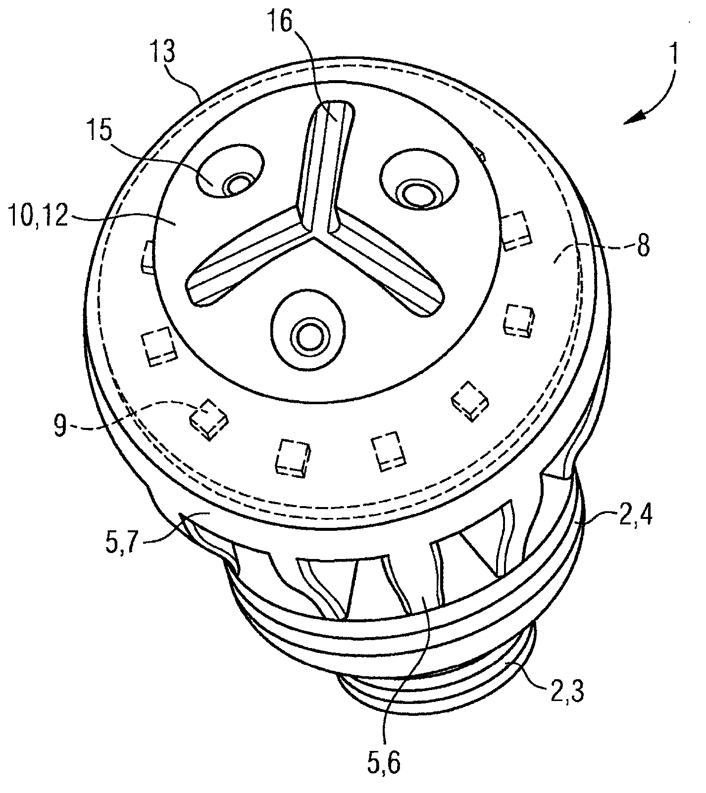
[0074] figure 1 Shows an oblique side view of a lighting device in the form of an LED incandescent retrofit lamp 1 according to a first embodiment, figure 2 Its oblique side view is shown as a simplified outline drawing, image 3 shows its oblique view, Figure 4 shows its top view, and Image 6 Its side view is shown.

[0075] The LED incandescent retrofit lamp 1 has a base 2 at the rear, which here has an Edison thread 3 for screwing into a socket of a conventional Edison incandescent lamp for supplying electricity. Before the Edison thread 3 (further in the direction of the z-axis, which here also corresponds to the longitudinal axis of the LED incandescent retrofit lamp 1 ), the lamp cap 2 has at least one part for accommodating a driver (not shown) The housing section 4. The driver is powered through the Edison Thread 3.

[0076] Attached to the base 2 is a first heat sink 5 with nine rearward or rearward (opposite to the z-direction) oriented z rotations about the...


PUM


Abstract

The invention relates to an illumination device (1) comprising a first heat sink (5), a carrier substrate (8) populated on the front side thereof by at least one light source (9), in particular a light-emitting diode, and the back side thereof being attached to the first heat sink (5), and comprising a second heat sink (10) disposed substantially in front of the carrier substrate (8), wherein the at least one light source (9) is disposed outside of the second heat sink (10; 32).

Description

technical field [0001] The invention relates to a lighting device, especially an LED retrofit lamp. Background technique [0002] A major problem in LED lamps is the extraction of dissipated heat from the light emitting diodes (LEDs). Not only the service life of the LED is improved by cooling, but also the efficiency of the LED is improved. The main concern when designing LED lamps is therefore to create the largest possible cooling surface. In order to replace conventional incandescent bulbs by LED lamps (LED-incandescent retrofit lamps), in this case the following problems arise for the replacement of conventional incandescent bulbs by LED lamps (LED-incandescent retrofit lamps): Typically A spherical diffuser or opaque bulb housing is mounted on the lamp for uniform emission and to achieve or at least approximate a customary shape. Only when the diffuser protrudes more than a hemisphere backwards, that is to say in the direction of the lamp head, a small part of the l...

Claims


Application Information

Patent Timeline
IPC IPC(8): F21K99/00F21Y101/02F21V29/505
CPCF21K9/1355F21V3/0418F21V3/0409F21V3/0436F21V3/02F21V3/005F21K9/00F21V29/004F21Y2101/02F21Y2103/022F21V29/2231F21V29/505F21V29/506F21V29/717F21V29/74F21V29/77F21V29/773F21V29/83F21V29/86F21V29/87F21K9/23F21Y2103/33F21Y2115/10F21Y2115/15F21K9/232F21V3/06F21V3/061F21V3/062
Inventor 妮科尔·布赖德纳塞尔京特·赫策尔法比安·赖因格鲁贝尔西蒙·施瓦伦贝里
Owner OSRAM GMBH
Why Eureka
Try Eureka