Method for producing plasma display panel

A display panel and manufacturing method technology, applied in the direction of alternating current plasma display panel, discharge tube/lamp manufacturing, cold cathode manufacturing, etc., can solve the problem of large attenuation rate

Inactive Publication Date: 2012-10-03
PANASONIC CORP
View PDF5 Cites 1 Cited by
  • Summary
  • Abstract
  • Description
  • Claims
  • Application Information

AI Technical Summary

Problems solved by technology

[0005] However, when the initial electron emission performance is improved by doping MgO with impurities, the attenuation rate at which the charge accumulated in the protective layer decreases with time increases.

Method used


Image

  • Method for producing plasma display panel
  • Method for producing plasma display panel
  • Method for producing plasma display panel

Examples


Embodiment Construction

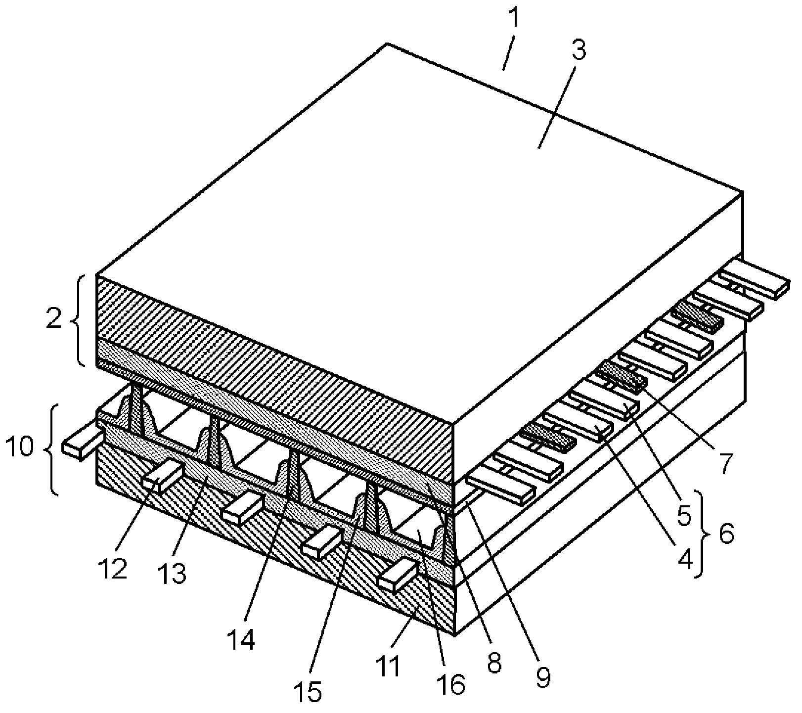
[0028] The basic structure of the PDP is a general AC surface discharge type PDP. Such as figure 1 As shown in the PDP 1, a front panel 2 composed of a front glass substrate 3 and the like and a rear panel 10 composed of a rear glass substrate 11 and the like are opposed to each other. The outer peripheral portions of the front panel 2 and the rear panel 10 are hermetically sealed with a sealing material made of glass frit or the like. Discharge gas such as neon (Ne) and xenon (Xe) is sealed in the discharge space 16 inside the sealed PDP 1 at a pressure of 53 kPa (400 Torr) to 80 kPa (600 Torr).

[0029] On the front glass substrate 3, a pair of strip-shaped display electrodes 6 and black stripes 7 composed of scan electrodes 4 and sustain electrodes 5 are arranged in multiple rows in parallel to each other. Dielectric layer 8 functioning as a capacitor is formed on front glass substrate 3 so as to cover display electrodes 6 and black stripes 7 . Furthermore, protective la...


PUM

PropertyMeasurementUnit
particle sizeaaaaaaaaaa
thicknessaaaaaaaaaa
particle sizeaaaaaaaaaa

Abstract

Disclosed is a method for producing a plasma display panel, which comprises the following procedure: an agglomerated particle paste containing a solvent and agglomerated particles, in which a plurality of crystal particles composed of magnesium oxide are agglomerated, is prepared; a crystal particle paste containing a solvent and crystal particles, which have a cubic shape and are composed of magnesium oxide, is prepared; then, the agglomerated particle paste and the crystal particle paste are mixed together, thereby forming a mixed crystal particle paste; after that, a mixed crystal particle paste film is formed by applying the mixed crystal particle paste over a base layer; and following that, the mixed crystal particle paste film is dried, thereby dispersing the agglomerated particles and the crystal particles all over the surface of the base layer.

Description

technical field [0001] The technology disclosed here relates to a method of manufacturing a plasma display panel used in a display device or the like. Background technique [0002] A plasma display panel (hereinafter referred to as PDP) is composed of a front panel and a rear panel. The front panel is composed of a glass substrate, display electrodes formed on one main surface of the glass substrate, a dielectric layer covering the display electrodes and functioning as a capacitor, and a protective layer formed on the dielectric layer and composed of magnesium oxide (MgO) . On the other hand, the back plate is composed of a glass substrate, address electrodes formed on one main surface of the glass substrate, a base dielectric layer covering the address electrodes, barrier ribs formed on the base dielectric layer, and a red-glowing electrode formed between the barrier ribs. , green and blue phosphor layers. [0003] The front panel and the rear panel are airtightly sealed...

Claims


Application Information

Patent Timeline
Patent Type & Authority Applications(China)
IPC IPC(8): H01J9/02H01J11/12H01J11/40
CPCH01J11/40H01J9/02H01J11/12
Inventor 上谷一夫坂元光洋沟上要吉田真介
Owner PANASONIC CORP
Why Eureka
Try Eureka