
Tire tread pattern structure for all-terrain vehicle

A tire tread and pattern structure technology, applied in tire tread/tread pattern, tire parts, vehicle parts, etc., can solve the problem of reducing the smoothness of turning slip, weakening the rigidity of pattern blocks, and affecting tire slip performance, etc. problems, to achieve the effect of improving turning control performance, improving slip performance, and increasing the ability to get out of trouble

Active Publication Date: 2014-07-02
CHENG SHIN RUBBER (XIAMEN) IND LTD
View PDF4 Cites 0 Cited by
  • Summary
  • Abstract
  • Description
  • Claims
  • Application Information

AI Technical Summary

Problems solved by technology

However, the block shape design is easy to interfere with the turning process of the tire, which reduces the smoothness of slippage during turning and affects the slippage performance of the tire.
Although the deep groove depth design improves the traction of the tire under bad road conditions, but when the tire is driving and braking, a large bending moment acts on the root of the pattern block, which reduces the durability of the pattern block
[0004] In order to improve the turning slip performance of the block pattern block design, a slope design extending to the side wall of the block pattern block is often designed on the edge of the block pattern block, which improves the turning slip performance to a certain extent, but weakens the pattern block The rigidity of the tire affects the cornering performance of the tire
In order to improve the durability of tire pattern blocks, the pattern blocks are often set in the shape of an inclined cone, that is, the side walls of the pattern blocks are designed to be inclined to the outside to increase the rigidity of the root of the pattern block, but it has little effect on improving the turning performance of the tire. good

Method used


Image

  • Tire tread pattern structure for all-terrain vehicle
  • Tire tread pattern structure for all-terrain vehicle
  • Tire tread pattern structure for all-terrain vehicle

Examples


Embodiment Construction

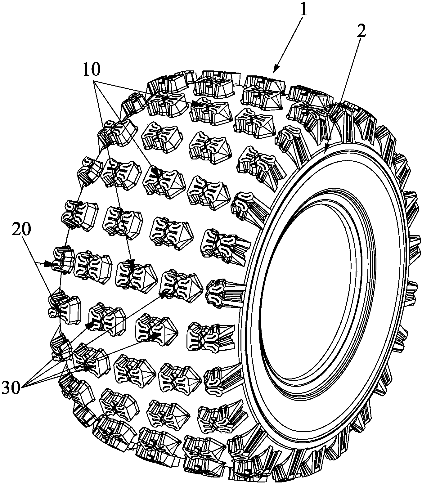
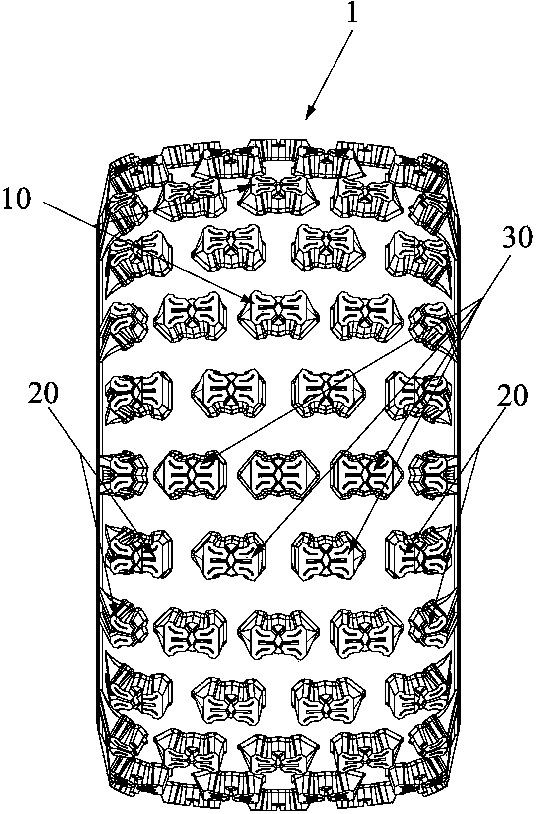
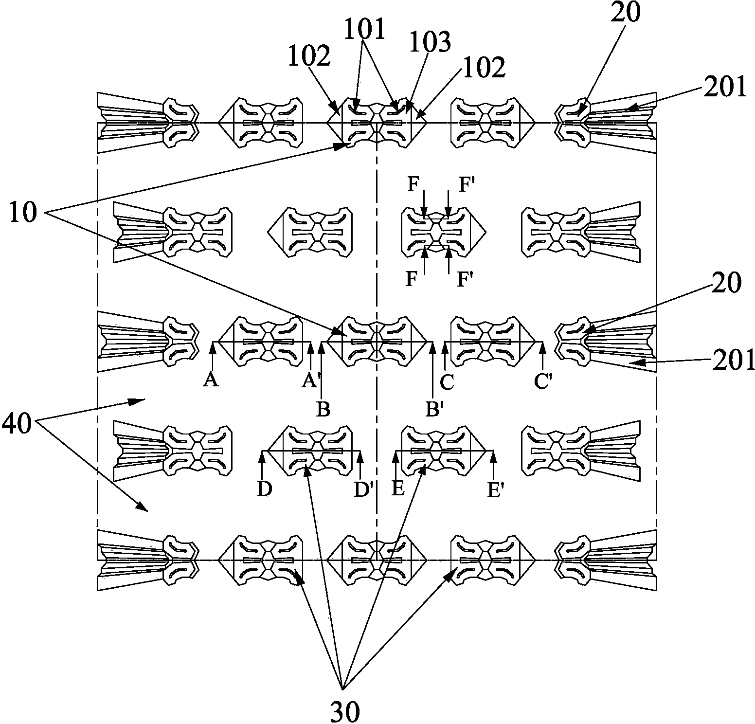
[0032] like Figure 1 to Figure 10 As shown, the present invention discloses an all-terrain vehicle tire tread pattern structure, which is mainly distributed with independently raised pattern blocks on the tread 1 of the tire, wherein each pattern block is distributed on the tread in the form of a horizontal arrangement 1, and the pattern blocks of each row are arranged in a staggered manner, that is, the pattern blocks of the second row are just aligned with the gap between two adjacent pattern blocks of the first row, thus forming pattern blocks arranged in odd rows On the tire circumferential line at the same position, the pattern blocks in the even rows are on the same position of the tire circumferential line, and the outer extending slopes of the pattern blocks located on both sides of the tread 1 are connected with the bead 2 .

[0033] The above-mentioned pattern blocks are divided into a central pattern block 10 located at the center of the tread, a shoulder pattern b...


PUM


Abstract

Disclosed is a tire tread pattern structure for an all-terrain vehicle. Independent raised pattern blocks are distributed on a tread of a tire, the pattern blocks are distributed on the tread in a transverse arraying manner, pattern blocks in each row are distributed crossly, namely each pattern block in a second row is right aligned with a gap between two adjacent pattern blocks in a first row, and outside extending bevels of the pattern blocks located on two sides of the tread are connected with a tire bead together. A diagonal plane is arranged at the transverse outside edge of each pattern block. Each pattern block of the tread of the tire is arrayed transversely and regularly, and accordingly traction performance of the tire can be improved effectively. The diagonal planes are arranged at the transverse outside edges of the pattern blocks, and accordingly slippage resistance when the vehicle makes a turn can be reduced, and slippage performance of the tire is improved. The outside extending bevels of the pattern blocks located on the two sides of the tread are connected with the tire bead together, so that traction performance of the tire on a shaft can be improved, escaping capacity of the tire from the soil is improved, and handling performance in making a turn of the tire is improved effectively.

Description

technical field [0001] The invention relates to a tire tread pattern structure, in particular to an all-terrain vehicle (ALL Terrain Vehicle) tire tread pattern structure which can improve the turning control performance of the rear wheel of the tire. Background technique [0002] With the overall development of the automobile market, all-terrain vehicles (ALL Terrain Vehicles), as a new type of vehicles, are getting more and more attention from consumers, especially sporty all-terrain vehicles. More and more sports-loving consumers regard it as the first choice for recreational sports. Considering the particularity of the terrain used by all-terrain vehicles, in order to improve the traction and comfort requirements of the vehicle, now sporty all-terrain vehicles are beginning to adopt an independent suspension structure design on the rear wheels. This design improves the tire's grip on the ground to achieve the required traction performance. However, due to the high trac...

Claims


Application Information

Patent Timeline
Patent Type & Authority Patents(China)
IPC IPC(8): B60C11/03
Inventor 陈秀雄
Owner CHENG SHIN RUBBER (XIAMEN) IND LTD
Learn More