Pneumatic blocking device of conveyor

A technology of blocking device and conveyor, applied in the direction of conveyor objects, transportation and packaging, etc., can solve the problems of wear and tear of the body, can not completely avoid the falling of goods at the head of the conveyor line, etc., and achieves low cost, simple structure and wide application range. Effect

Inactive Publication Date: 2012-10-10
WUXI JIESI LOGISTICS EQUIP
View PDF13 Cites 8 Cited by
  • Summary
  • Abstract
  • Description
  • Claims
  • Application Information

AI Technical Summary

Problems solved by technology

[0002] In the process of conveying goods, it is often necessary to stop the goods at the back of the conveying line for a while to ensure the smooth delivery of the goods in front and avoid the falling of the goods at the head of the conveying line. This is a common practice in the prio

Method used


Image

  • Pneumatic blocking device of conveyor
  • Pneumatic blocking device of conveyor
  • Pneumatic blocking device of conveyor

Examples


Embodiment Construction

[0011] The specific implementation manner of the present invention will be described below in conjunction with the accompanying drawings.

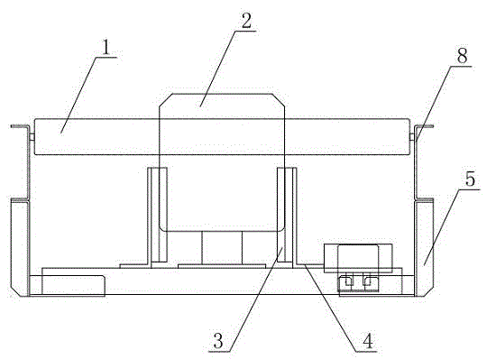
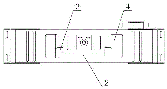
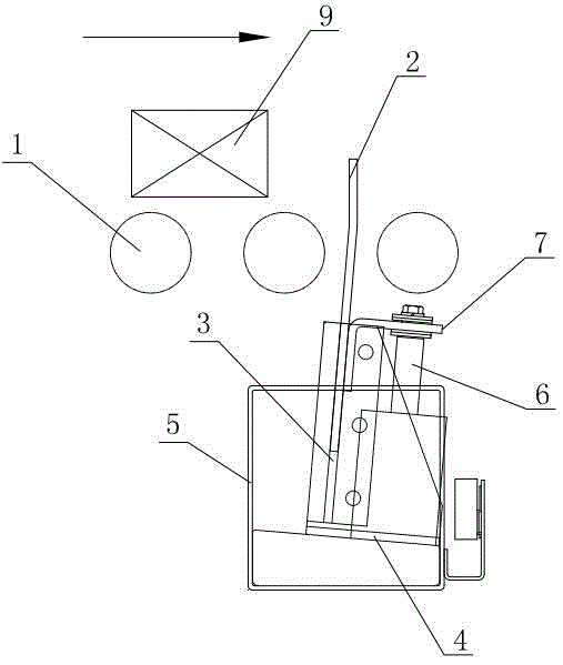
[0012] refer to figure 1 , figure 2 , image 3 , the present invention comprises a roller conveyor 1 and a conveyor frame 8, a baffle 2 is arranged between adjacent rollers on the roller conveyor 1, the middle and lower sections of the baffle 2 are stuck in the slot on the upper part of the guide block 3, and the baffle 2 One side of the middle and lower end of the plate 2 is connected with the piston rod of the cylinder 6 through the connecting plate 7, the guide block 3 is fastened to the guide block bracket 4, the guide block bracket 4 is fastened to the blocking device mounting bracket 5, and the blocking device mounting bracket 5 is fastened Attach conveyor rack 8.

[0013] The operation of the present invention is as follows:

[0014] The baffle plate 2 and the cylinder 6 are connected by bolts of the connecting plate 7, and the...


PUM


Abstract

The invention provides a pneumatic blocking device of a conveyor, comprising a rotary drum conveyor and a conveyor rack, wherein a baffle is arranged between adjacent rotary drums of the rotary drum conveyor; the lower middle section of the baffle is clamped into a clamping groove at the upper part of a guide block; one side of the lower middle end of the baffle is connected with a piston rod of an air cylinder through a connecting plate; the guide block is fixedly connected with a guide block bracket; the guide block bracket is fixedly connected with a blocking device mounting bracket; and the blocking device mounting bracket is fixedly connected with the conveyor rack. The pneumatic blocking device of the conveyor disclosed by the invention can realize automatic operation of blocking cargos on a conveying line, and has the advantages of simple structure, flexibility and convenience for operation, low cost and wide application range.

Description

technical field [0001] This invention relates to conveyor construction, and more particularly to pneumatic barriers for use at the end or in the middle of a conveyor. technical background [0002] In the process of conveying goods, it is often necessary to stop the goods at the back of the conveying line for a while to ensure the smooth delivery of the goods in front and avoid the falling of the goods at the head of the conveying line. This is a common practice in the prior art It is to stop the conveying. Although it can ensure the smooth conveying of the goods in front, the process of opening and stopping the conveyor will directly wear the body, and at the same time, it cannot completely avoid the falling of the goods at the head of the conveyor line. Contents of the invention [0003] The applicant improves on the above-mentioned shortcomings in the prior art, and provides a pneumatic blocking device for conveyors, which has simple structure, flexible and convenient op...

Claims


Application Information

Patent Timeline
IPC IPC(8): B65G47/88
Inventor 王建兵
Owner WUXI JIESI LOGISTICS EQUIP
Why Eureka
Try Eureka