Main driving device for rapier loom

A rapier loom, main drive technology, applied in looms, textiles, textiles and papermaking, etc., can solve the problems of complex control, affecting the implementation and promotion of the system, no control system, etc., to simplify the transmission system and improve the stability. And the efficiency of transmission, the effect of improving the stability of operation

Inactive Publication Date: 2012-10-10
天津哲民广仁电机有限公司
View PDF6 Cites 8 Cited by
  • Summary
  • Abstract
  • Description
  • Claims
  • Application Information

AI Technical Summary

Problems solved by technology

In actual implementation, the main drive motor is a motor that operates on the principle of reluctance. Due to design principles, although the reluctance motor has the advantages of simple structu

Method used


Image

  • Main driving device for rapier loom
  • Main driving device for rapier loom
  • Main driving device for rapier loom

Examples


Example Embodiment

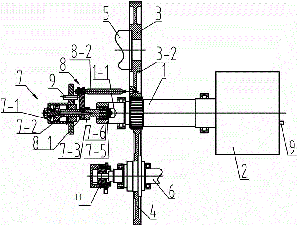
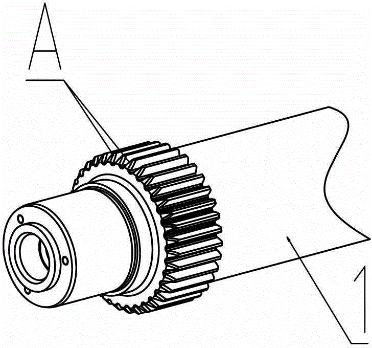
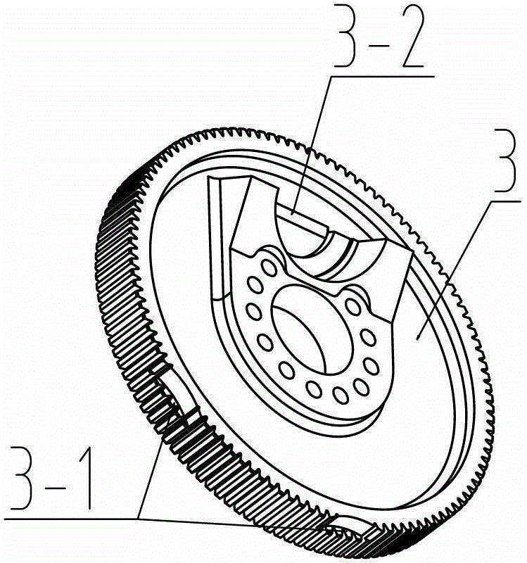
[0032] In order to further understand the content, features and effects of the present invention, the following embodiments are given as examples, and detailed descriptions are as follows with accompanying drawings:

[0033] See Figure 1 to Figure 6 , A main drive device used on a rapier loom, comprising a motor rotor gear shaft 1, a motor stator 2, a beating-up gear 3, a split gear 4, a beating-up transmission shaft 5 and a split shaft 6, the motor rotor gear shaft The rotor part of 1 is inserted into the motor stator 2. The transverse magnetic circuit of the rotor part of the motor rotor gear shaft 1 is inconsistent with the transverse magnetic circuit of the electronic stator 2. That is, the transverse magnetic circuit of the motor rotor gear shaft is greater than the transverse magnetic circuit of the motor stator. Or the transverse magnetic circuit of the motor rotor gear shaft is smaller than the transverse magnetic circuit of the motor stator. The end of the motor rotor g...


PUM


Abstract

The invention relates to a main driving device for a rapier loom. The main driving device comprises a motor rotor gear shaft, a motor stator, a beating-up gear, an opening gear, a beating-up transmission shaft and an opening shaft and is characterized in that the rotor part of the motor rotor gear shaft is inserted into the motor stator, and the transverse magnetic circuit of the rotor part of the motor rotor gear shaft is not consistent with the transverse magnetic circuit of the motor stator in length; the end part of the motor rotor gear shaft is coaxially provided with a hydraulic push device for driving the motor rotor gear shaft to horizontally move; and an axial gap is arranged on the beating-up gear. Through the design of the technical scheme, the switching of two working positions of the rapier loom and the rapid opening and stopping of the rapier loom are realized through controlling a permanent magnet motor, and the defects of pulsation, vibration, noises and the like of a driving system during low-speed switch are overcome. Meanwhile, the device cannot cause the influence of the axial electric magnetic force due to coil energization at the two working positions, and further the demand on hydraulic pressure power can be reduced. Meanwhile, the main driving device has a better energy saving effect compared with the driving of a reluctance motor.

Description

technical field [0001] The invention belongs to the technical field of rapier loom manufacture, in particular to a main driving device used on a rapier loom. Background technique [0002] The current loom driving device mainly uses a three-phase asynchronous AC motor to drive the main shaft through a belt, and the main shaft controls the rapid start and stop of the loom through a group of electromagnetic clutch brakes. Through the main shaft, the motor drives the whole machine to run at high speed. When it needs to stop, the electromagnetic clutch disconnects the transmission, and at the same time, the electromagnetic brake brakes quickly to stop the whole machine from running. When it is necessary to search for broken weft yarns, a separate motor drives the whole machine through a group of electromagnetic clutches to perform forward or reverse full-circle slow motion. [0003] The structure of the above-mentioned device is complicated. At the same time, because the clutch ...

Claims


Application Information

Patent Timeline
IPC IPC(8): D03D51/00
Inventor 刘哲民王纯仁贾志斌张志凯
Owner 天津哲民广仁电机有限公司
Why Eureka
Try Eureka