Foundation pit supporting and protecting structure of underground continuous wall and construction method of structure

A technology of underground diaphragm wall and foundation pit support, which is applied in infrastructure engineering, excavation, sheet pile wall, etc. The effect of reducing material cost and reducing construction cost

Inactive Publication Date: 2012-10-10
南京奔腾建设有限公司
View PDF4 Cites 4 Cited by
  • Summary
  • Abstract
  • Description
  • Claims
  • Application Information

AI Technical Summary

Problems solved by technology

The increase of the depth of the ground connection wall will cause the following problems: (1) It will cause the increase of the depth of the reinforcement cage, and the increase of the depth of the reinforcement cage will cause the increase of the cost of the reinforcement material; (2) The increase of the depth of the reinforcement cage will cause the increase of the weight of the reinforcement cage , thereby increasing the cost and risk of hanging the reinforcement cage into the unit groove section; (3) The depth of the reinforcement cage increases, and the depth of the two groove walls of the unit groove section also increases correspondingly. The unevenness of the tank wall will increase the possibility that the reinforcement cage cannot be lowered, which will not only slow down the construction speed, but also increase the construction cost; (4) The possibility of forming small cracks between the contact surface of the concrete and the joint also increases, The anti-seepage function of the ground connection wall is reduced
[0007] In order to ensure the safety of the foundation pit itself, the underground facilities around the foundation pit and the ground buildings, there is an urgent need for a foundation pit support structure that can solve the four problems mentioned above, but there is no way to solve the aforementioned problems at present. A Construction Method of Foundation Pit Supporting Structure with Ground Connecting Wall Based on Four Problems

Method used


Image

  • Foundation pit supporting and protecting structure of underground continuous wall and construction method of structure
  • Foundation pit supporting and protecting structure of underground continuous wall and construction method of structure
  • Foundation pit supporting and protecting structure of underground continuous wall and construction method of structure

Examples


Embodiment 1

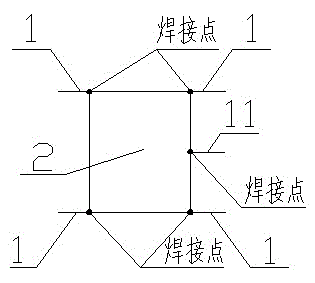
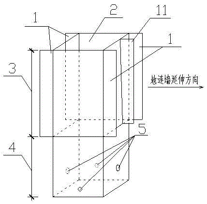
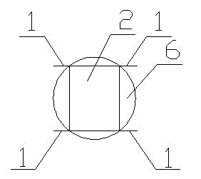
[0051] A foundation pit in Hexi, Nanjing City, Jiangsu Province is 12m deep and 7.9m long on one side. From the site surface to 4m below the ground is silty clay, below 4m is silt, and 1.5m below the ground is groundwater. 10m outside the side wall of the foundation pit is Nanjing Metro Line 2. In order to ensure the absolute safety of Metro Line 2, it is necessary to prevent the water and soil outside the foundation pit from flowing into the foundation pit. The multifunctional function of the wall—retaining soil, stopping water, and carrying vertical force as the outer wall of the building. The ground connection wall is 7.9m in length, 12m in depth, and 1m in width. It is composed of a unit groove section 7 and two steel plate columns 2. The unit groove section 7 has a length of 6m, a depth of 12m, and a width of 1m. The depth of the steel plate column 2 = 12m. Depth 3+12m extension part 4, steel plate column 2 is welded by steel plate with wall thickness 0.012m, length of ...

Embodiment 2

[0071] A foundation pit on Zhongshan Road, Nanjing City, Jiangsu Province is 12m deep and 7m long on one side. From the site surface to 4m below the ground is clay, below 4m is sandy soil, and 1m below the ground is groundwater. The 5m outside the side wall of the foundation pit is Nanjing Metro Line 1 and Zhongshan Road, a transportation hub in Nanjing. In order to ensure the absolute safety of Metro Line 1 and Zhongshan Road, the transportation hub, it is necessary to prevent the water and soil outside the foundation pit from flowing into the foundation pit. At the same time, in order to reduce construction investment, the owner decided to install a ground connection wall between the foundation pit and the side wall of the foundation pit. , to give full play to the multi-functional role of the ground connection wall - retaining soil, stopping water, and carrying vertical force as the outer wall of the building. The ground connection wall is 7.9m in length, 12m in depth, and...


PUM


Abstract

A foundation pit supporting and protecting structure of an underground continuous wall is composed of wing plates, metal sheet pillars, a concrete diaphragm wall design depth, extended parts, a round hole, drill holes, a unit groove section, protective walls, wood wedges, channel steels, a water-stopping plate and a steel reinforcement cage. The metal sheet pillars are welded by four steel plates into the shape of II, the left sides and the right sides of the metal sheet pillars are respectively provided with two wing plates, and another steel plate is welded at a half-way line position between the two wing plates on one side to serve as the water-stopping plate. The length of the metal sheet pillars is equal to the concrete diaphragm wall design depth plus the length of the extended parts. The two wing plates arranged on the left sides and the right sides of the extended parts are cut, two ends of the bottom of the unit groove section are respectively drilled with holes, and the extended parts of the two metal sheet pillars are respectively arranged into the drill holes and fixed through concrete pouring. Two sides of the unit groove section are the protective walls, the metal sheet pillars and the protective walls are tightly wedged through the wood wedges, small steel pieces arranged at two ends of the two channel steels respectively cover the metal sheet pillars, the steel reinforcement cage is arranged in the unit groove section, the metal sheet pillars and the unit groove section are all poured with concrete to the height of the floor, and after the concrete is solidified, the wood wedges and the channel steels are removed, thereby manufacturing the foundation pit supporting and protecting structure connected underground.

Description

[0001] technical field [0002] The present invention relates to a foundation pit support structure type, specifically an underground continuous wall (hereinafter referred to The construction method of the foundation pit support structure for ground connection wall). Background technique [0003] In order to ensure the smooth construction of the foundation pit and the safety of surrounding underground facilities and buildings, support structures are usually arranged between the foundation pit and the side walls of the foundation pit, and there are various forms of foundation pit support structures. The ground connection wall is a kind of foundation pit support structure, which is currently being used more and more in foundation pit engineering, because the ground connection wall can not only complete the traditional function of the foundation pit support structure - as a retaining structure to prevent the foundation pit The soil outside the side wall moves into the foundati...

Claims


Application Information

Patent Timeline
Patent Type & Authority Applications(China)
IPC IPC(8): E02D17/04E02D19/18E02D5/20E02D5/38
Inventor 徐方敏
Owner 南京奔腾建设有限公司
Why Eureka
Try Eureka