Lifting support

A lifting bracket and swing rod technology, applied in the field of climbing appliances, can solve the problems of trouble, inability to lift and lower freely, danger, etc., and achieve the effects of convenient use, improved safety factor, and avoidance of up and down climbing

Active Publication Date: 2014-08-20
SUZHOU PICA ALUMINUM IND
View PDF6 Cites 0 Cited by
  • Summary
  • Abstract
  • Description
  • Claims
  • Application Information

AI Technical Summary

Problems solved by technology

The frame structure of these scaffolds is relatively complicated, and except for the large-scale scaffolds equipped with elevators, most of them cannot be freely lifted and lowered. When the upper or lower floors are required to operate, workers need to climb up and down the scaffolds, which is very dangerous and troublesome.

Method used


Image

  • Lifting support
  • Lifting support
  • Lifting support

Examples


Embodiment

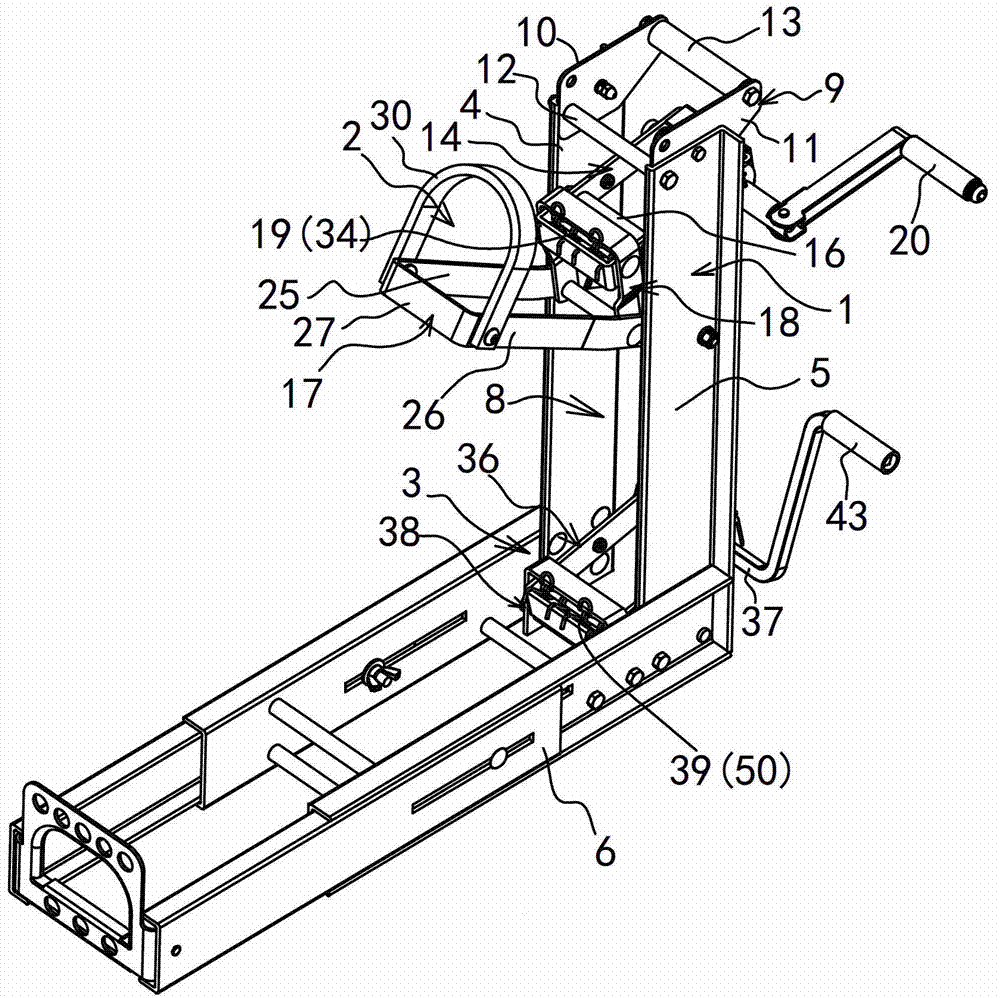
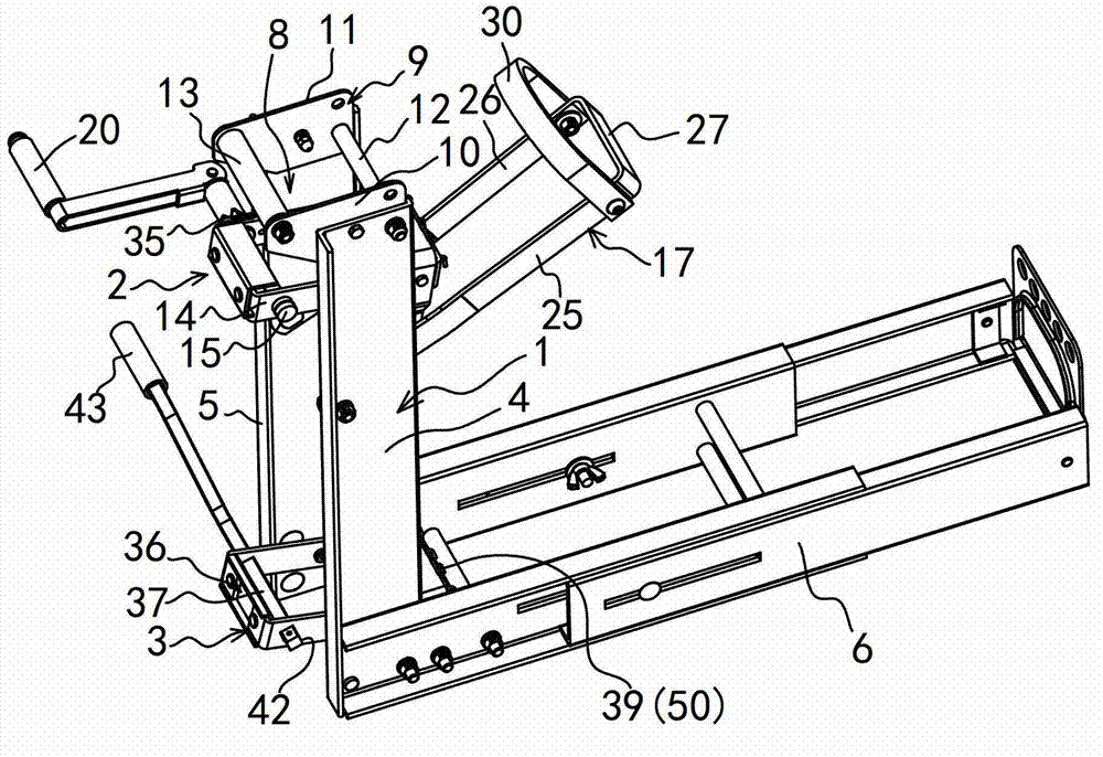
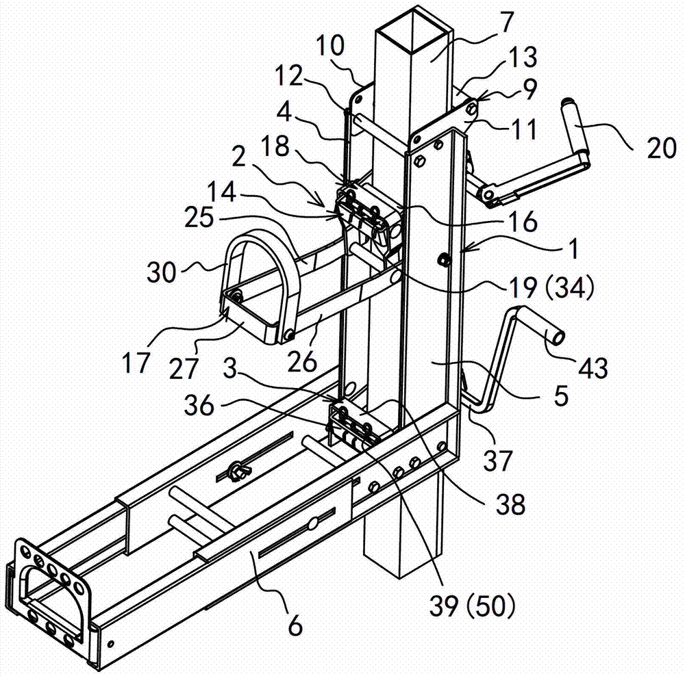
[0033] Example: see attached figure 1 ~ attached Figure 10 Shown:

[0034] A lifting bracket is composed of a fixed sleeve frame 1, a foot pump driving mechanism 2 and a drop limiting mechanism 3.

[0035] The fixed sleeve frame 1 includes a left side plate 4 , a right side plate 5 , a bracket 6 for placing pedals and a top guide frame 9 . The left side plate 4 and the right side plate 5 are left and right opposite, and between the left side plate 4 and the right side plate 5, a longitudinal space 8 for accommodating the column 7 is formed. The lower end is fixed forward. Top guide frame 9 is made up of left connector 10, right connector 11, front guide wheel 12 and rear guide wheel 13. The left connecting piece 10 and the right connecting rod 11 are arranged opposite to each other. The front guide wheel 12 is connected between the front ends of the left connecting piece 10 and the right connecting rod 11, and the rear guide wheel 13 is connected behind the left connecting ...


PUM


Abstract

A lifting support is characterized by comprising a fixing sleeve frame, a foot pump driving mechanism and a falling-limiting mechanism. The fixing sleeve frame comprises a left side plate, a right side plate and a supporting frame for placing a pedal, the foot pump driving mechanism comprises a first oscillating rod assembly, a friction wheel, a first roller wheel, a foot rest lever assembly, a first connecting rod assembly, a first torsional spring and a first rotary operation handle. Acting force of the first torsional spring forces the friction wheel to prop against the rear lateral side of a stand column in a matching manner and forces the first roller wheel to prop against the front lateral side of the stand column in a matching manner. The falling-limiting mechanism comprises a second oscillating rod assembly, a falling-limiting rod, a second connecting rod assembly and a second torsional spring. According to the invention, two lifting supports are applied and respectively sleeved on one stand column, then one pedal is erected on the supporting frame of the lifting supports of the two stand columns, and therefore a brand new scaffold is formed. Two workers standing on the pedal can synchronously operate the two lifting supports, thereby driving the pedal and the workers to lift or descend.

Description

technical field [0001] The invention relates to the field of climbing appliances such as scaffolding, and in particular to a human-mechanical lifting support for building scaffolding. When in use, two lifting brackets are used, and each lifting bracket is placed on a column, and then a pedal is set up between the lifting brackets of the two columns to form a scaffold. The worker stands on the pedal and operates the two lifting brackets synchronously to drive the pedal. Workers themselves ascend or descend. Background technique [0002] Scaffolding is a support set up on the construction site for workers to operate and solve vertical and horizontal transportation. It is used in places where external walls, interior decoration or high floor heights cannot be directly constructed. [0003] There are many kinds of existing scaffolds, including fastener-type steel pipe scaffolding, door-type steel pipe scaffolding, buckle-plate scaffolding, aluminum alloy quick-installing scaffo...

Claims


Application Information

Patent Timeline
Patent Type & Authority Patents(China)
IPC IPC(8): E04G3/28
Inventor 陆卫明
Owner SUZHOU PICA ALUMINUM IND
Why Eureka
Try Eureka