Linear-motion electromagnetic loading device

A loading device and linear motion technology, which is applied in the testing of measuring devices, instruments, and mechanical components, etc., can solve the problems that mechanical equipment is difficult to simulate loading, etc., and achieve the effect of simple structure, fast response and good controllability

Inactive Publication Date: 2012-10-10
XIAN UNIV OF TECH
View PDF7 Cites 8 Cited by
  • Summary
  • Abstract
  • Description
  • Claims
  • Application Information

AI Technical Summary

Problems solved by technology

[0003] The purpose of the present invention is to provide a linear motion electromagnetic loading device, which solves the problem in the prior art that the magnetic powder loader can only load the rotary motion components, but it is difficult to simulate the loading of mechanical equipment whose output components are linear motions

Method used


Image

  • Linear-motion electromagnetic loading device
  • Linear-motion electromagnetic loading device
  • Linear-motion electromagnetic loading device

Examples


Embodiment Construction

[0015] The present invention will be described in detail below in conjunction with the accompanying drawings and specific embodiments.

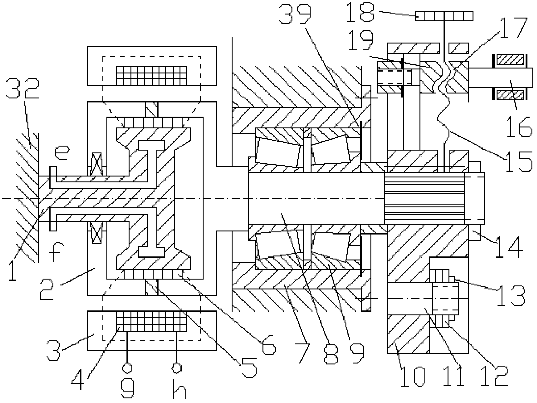
[0016] The structure of the device of the present invention is, comprises mechanical part and electrical control part, and mechanical part comprises link mechanism and magnetic powder loader part again, and the axle center of linear rolling guide bush 27 in the link mechanism and magnetic powder loader main shaft 8 is arranged on the working On the same height line as platform 32,

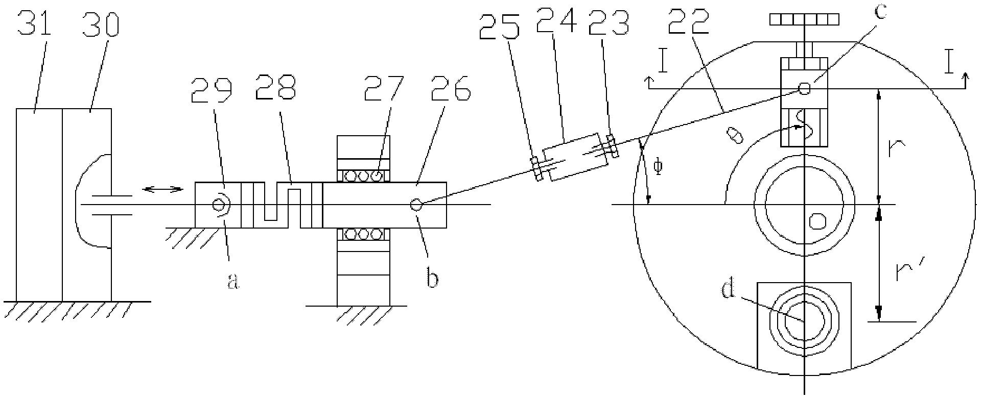
[0017] The structure of the link mechanism is to include a linear rolling guide bush 27, a loading head 26 is worn in the linear rolling guide bushing 27, and one end of the loading head 26 is sequentially connected with a one-way tension pressure sensor 28, a linear output member 29, and a loaded mechanism. 30. The prime mover 31; the other end of the loading head 26 is hinged with the left half connecting rod 38, the left half connecting rod 38 is threadedly con...


PUM


Abstract

The invention discloses a linear-motion electromagnetic loading device which comprises a linkage mechanism, a magnetic powder loader part and an electrical control part. A loading head passes through a linear rolling guide sleeve in the linkage mechanism. One end of the loading head is connected with a one-way tension and pressure sensor. The other end of the loading head is connected with a crank pin through a connecting rod and a threaded sleeve. The magnetic powder loader part is characterized in that: a circulating cooling water channel is arranged in an inner cavity of a stator; a magnetic powder is arranged in a gap between a rotor and the stator; a loading coil is arranged on a circle surface in a stator shell; the rotor is connected with a main shaft and a disc; the disc is provided with the crank pin through a trapezoid sliding block. The electrical control part comprises a loading controller and an industrial control computer. By using the apparatus of the invention, performance analysis and test loading of a prime mover and a mechanical system possessing a linear motion output member can be realized. A constant loading current is used to obtain a variable loading force. The small loading current is used to obtain the large loading force.

Description

technical field [0001] The invention belongs to the technical field of performance detection and testing of electromechanical equipment systems, and is used for performance analysis and testing of a mechanical system with a linear motion output component and a prime mover thereof, in particular to a linear motion electromagnetic loading device. Background technique [0002] With the rapid development of science and technology and the increasingly intensified market competition, the requirements for the performance and reliability of electromechanical products continue to increase. As an important means of performance testing and reliability testing of mechanical system prime movers and transmission actuators, simulated loading technology is used in The position in the development of mechanical and electrical products is becoming more and more important. At present, the technology for simulating loading of electromechanical systems whose output components are rotary motions i...

Claims


Application Information

Patent Timeline
IPC IPC(8): G01M13/00G01M99/00
Inventor 原大宁刘宏昭刘丽兰
Owner XIAN UNIV OF TECH
Why Eureka
Try Eureka