A stylus system

A stylus and touch control technology, applied in the direction of instruments, electrical digital data processing, data processing input/output process, etc., can solve the problems of small diameter of the pen tip, hard material of the pen tip, and separation of noise signals, etc. Promotion, low cost effect

Active Publication Date: 2016-05-11
SUZHOU PIXCIR MICROELECTRONICS
View PDF3 Cites 0 Cited by
  • Summary
  • Abstract
  • Description
  • Claims
  • Application Information

AI Technical Summary

Problems solved by technology

But when the stylus slides on the screen, there are two problems. First, the tip diameter of the stylus is very small, usually only 2mm in diameter. In addition, the material of the tip is generally hard.
The stylus is produced for a more comfortable writing feel and more precise operation, but its own conditions are contradicted by the larger contact area required by the capacitive screen
The small amount of capacitance change produced by the stylus (the signal generated by the pen) often makes it difficult for the touch circuit to distinguish it from the noise signal of the measurement system itself, which is the problem of signal-to-noise ratio
Another problem worth mentioning is how to separate the signal generated by the pen from the signal generated by the finger.
There are two situations here. First, the small signal generated by the stylus will be confused with the small signal generated when the finger is far away from the touch screen or touchpad. The other situation is when the hand holding the stylus touches the When touching a touch screen or trackpad, it will also be sensed, which makes it more difficult to detect and track the signal generated by the stylus

Method used


Image

  • A stylus system
  • A stylus system
  • A stylus system

Examples


Embodiment Construction

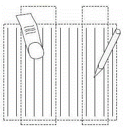
[0030] A stylus system is composed of a touch device, a driving circuit and a stylus. The touch device can be various capacitive touch screens, touch pads or touch blocks, and the like. The driving circuit is used to drive the stylus, which can be built in the stylus or installed in other positions.

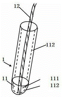
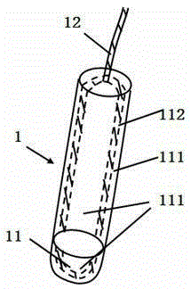
[0031] Please refer to Figure 1A As shown, the specific structure is as follows. The stylus 1 includes a conductive nib 11 and a connection 12 . In particular, the pen tip 11 is composed of a capacitive conductor tip (not shown) and an optional insulating layer 111 . The insulating layer 111 is used to prevent accidental short circuit, it is also used to protect the tip of the conductor from accidentally damaging or scratching the touch device, and it can also play a decorative and aesthetic role. The tip of the conductor is generally made into an arc shape, which can ensure good contact at all angles when touching the touch device, that is, can ensure a continuous capacitive ...


PUM


Abstract

The invention provides a touch-control pen system, comprising a conductor tip and a connection, wherein the connection is used for connecting the conductor tip with a first node of a drive circuit. According to the system, the problem of the sensing of a touch-control pen can be solved, and the problem of differentiation for a signal of the system from other signals can be relatively and perfectly solved; and moreover, the scheme provided by the invention is low in cost, and convenient for large-scale popularization.

Description

technical field [0001] The invention relates to a touch pen system, in particular to a capacitive touch pen system matched with a capacitive touch device. Background technique [0002] A capacitive touch screen generally includes an electrode group or electrode network and a circuit (such as a touch control circuit) for sensing or detecting changes in capacitance on the electrodes. When a finger approaches the electrodes some capacitance is introduced so that the finger can be sensed and located. When operating with one finger, it will obviously lead to a larger induction amount of the larger finger, because the larger finger has a larger contact area; another factor is that the fingertips of the human hand are soft and will spread out on the contact surface. form a larger contact area. Therefore, a finger on an excellent touch panel can generate a large amount of capacitance change, which can be easily detected. In general, a typical finger contact will form a circular s...

Claims


Application Information

Patent Timeline
Patent Type & Authority Patents(China)
IPC IPC(8): G06F3/0354G06F3/044
Inventor 雷奥纳·波特曼刘赫
Owner SUZHOU PIXCIR MICROELECTRONICS
Why Eureka
Try Eureka