Meta-material satellite antenna and satellite receiving system

A satellite antenna and metamaterial technology, applied in the field of communications, can solve the problems of high cost and difficult satellite antenna processing, and achieve the effects of easy manufacturing and processing and low cost.

Active Publication Date: 2012-10-10
KUANG CHI INST OF ADVANCED TECH
View PDF3 Cites 0 Cited by
  • Summary
  • Abstract
  • Description
  • Claims
  • Application Information

AI Technical Summary

Problems solved by technology

[0005] The technical problem to be solved by the present invention is to provide a metamaterial satellite antenna with simple processing, low

Method used


Image

  • Meta-material satellite antenna and satellite receiving system
  • Meta-material satellite antenna and satellite receiving system
  • Meta-material satellite antenna and satellite receiving system

Examples


Example Embodiment

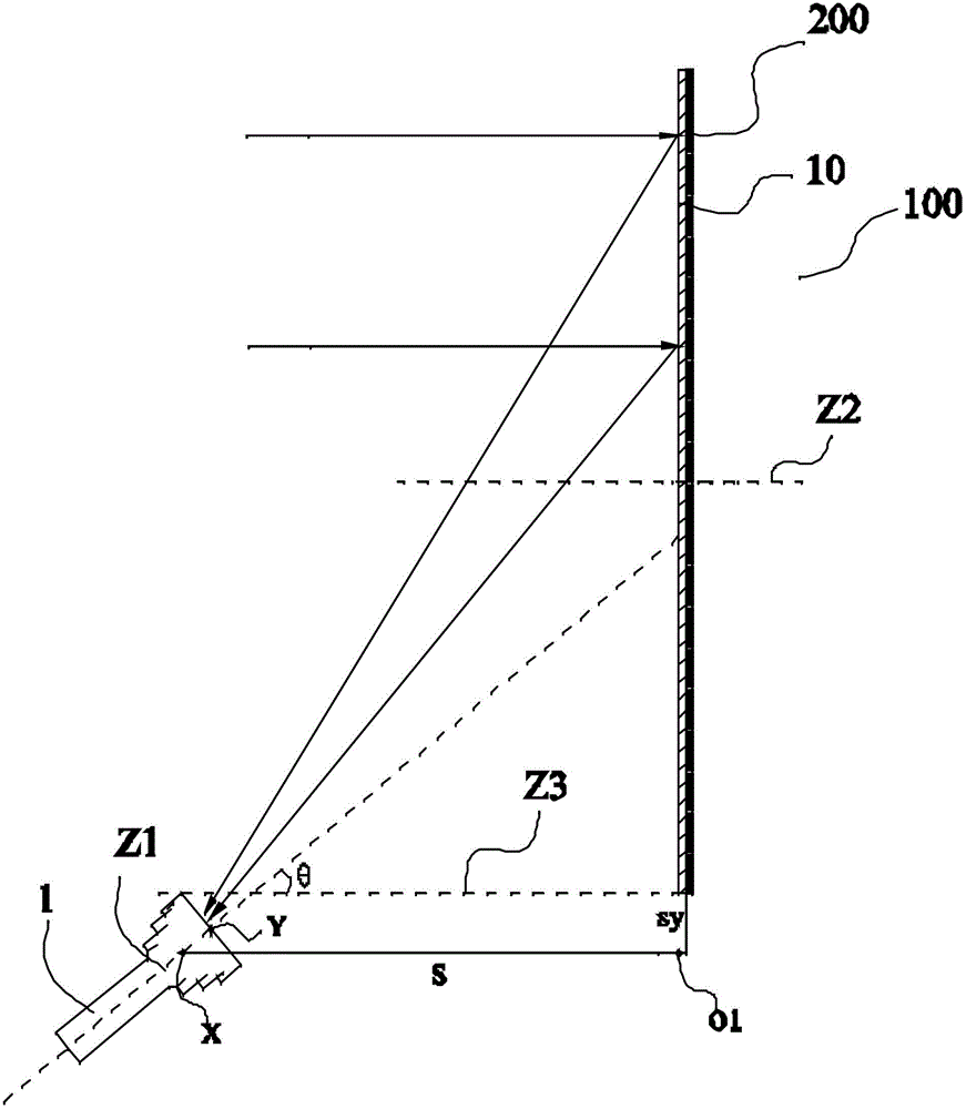
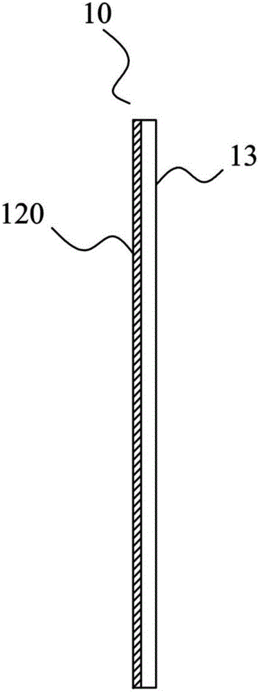
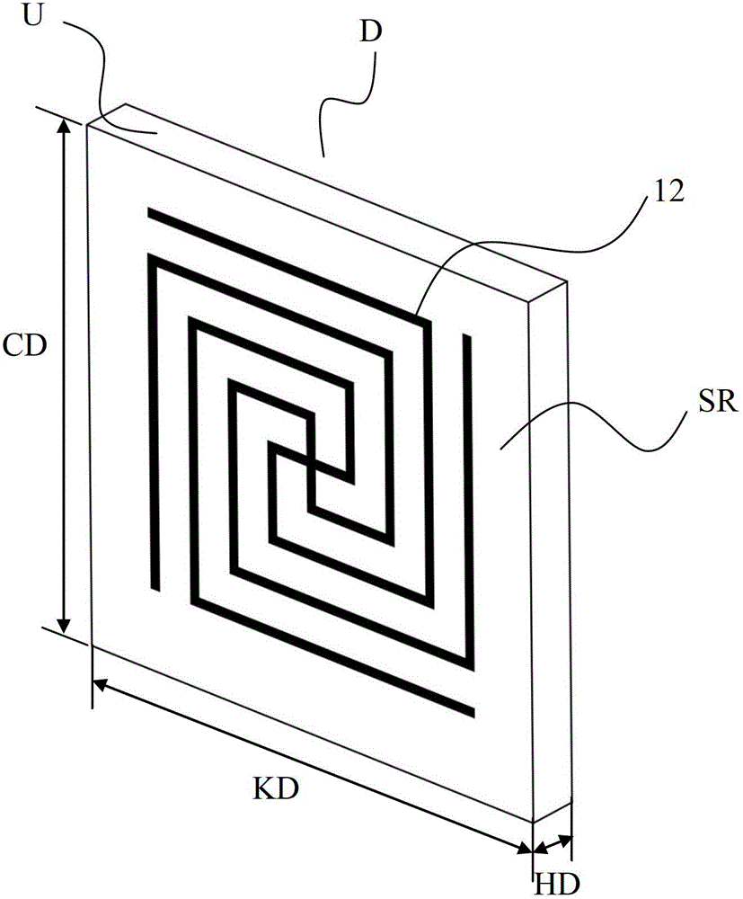
[0037] Such as Figure 1 to Figure 3 As shown, the metamaterial satellite antenna according to the present invention includes a metamaterial flat plate 100 arranged behind the signal transceiver 1, and the metamaterial flat plate 100 includes a core layer 10 and a grid-like reflector 200 arranged on the back surface of the core layer. The core layer 10 includes a substrate 13 and a plurality of artificial microstructures 12 attached to the front surface of the substrate 13, the back surface of the substrate 13 is attached with the grid-shaped reflector 200, the central axis Z1 of the signal transceiver 1 and the metamaterial The central axis Z2 of the plane of the flat plate 100 has a certain angle θ, namely figure 1 The angle between the central axis Z1 and the straight line Z3 (Z3 is the parallel line of Z2), the signal transceiver 1 is not on the central axis Z2 of the metamaterial flat plane, and the bias feed of the antenna is realized. In the present invention, any longi...


PUM

PropertyMeasurementUnit
Thicknessaaaaaaaaaa
Thicknessaaaaaaaaaa
Thicknessaaaaaaaaaa

Abstract

The invention discloses a meta-material satellite antenna, comprising a meta-material flat plate which is arranged behind a signal transceiver, wherein the meta-material flat plate comprises a core layer and a gridding reflection plate arranged on the rear surface of the core layer; the core layer comprises a substrate and a plurality of artificial micro-structures attached to the front surface of the substrate; the gridding reflection plate is attached to the rear surface of the substrate so that electromagnetic waves sent by a satellite are responded by the meta-material flat plate and are converged in the signal transceiver; and the sheet-shaped meta-material flat plate replaces a traditional parabolic antenna, so that the manufacturing and machining are easier and the cost is lower; furthermore, the whole thickness of the meta-material flat plate designed by the invention is at a millimeter grade and the meta-material flat plate is very light and thin; and the special artificial micro-structures are adopted so that the satellite antenna has a frequency selection function. The invention further provides a satellite receiving system.

Description

technical field [0001] The invention relates to the field of communication, more specifically, to a supermaterial satellite antenna and a satellite receiving system. Background technique [0002] Existing satellite antennas, such as satellite TV receiving antennas, usually use traditional reflector antennas, which are usually parabolic antennas, and the parabolic antenna is responsible for reflecting received signals to the signal transceiver at the focal point. [0003] When receiving the electromagnetic wave signal from the satellite, the parallel electromagnetic wave (because the distance between the satellite and the earth is quite far, the electromagnetic wave emitted by it can be regarded as a plane wave when it reaches the ground) is reflected by the parabolic antenna and then converged to the signal transceiver. This kind of satellite antenna has certain limitations to the choice of frequency. [0004] However, it is difficult to process the curved surface of the re...

Claims


Application Information

Patent Timeline
IPC IPC(8): H01Q1/36H01Q15/23H01Q19/06H01Q19/10
Inventor 刘若鹏季春霖岳玉涛李勇祥殷俊
Owner KUANG CHI INST OF ADVANCED TECH
Why Eureka
Try Eureka