
Forced synchronous resonance inertia cone crusher

A cone crusher and forced synchronization technology, which is applied in grain processing and other directions, can solve the problems of wear of crushing chamber components, decline in self-synchronization performance, and attenuation of resultant crushing force, etc. Effect

Active Publication Date: 2022-01-18
肖为民
View PDF11 Cites 0 Cited by
  • Summary
  • Abstract
  • Description
  • Claims
  • Application Information

AI Technical Summary

Problems solved by technology

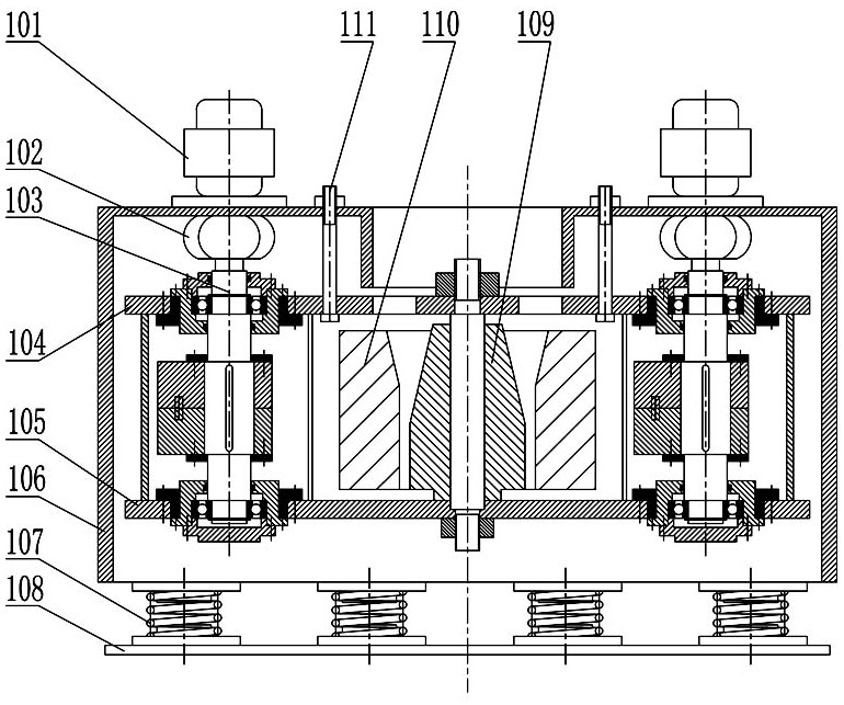
[0006] Although the self-synchronizing vibrating crusher has many advantages, the existing shortcomings are also very prominent: 1. The motor 101 drives the vibrator 103 to work through the elastic coupling 102. Since the vibrator 103 has no mandatory constraints, it is especially broken When the material is extremely uneven in particle size and hardness, the unbalanced effect of the huge reaction force will easily lead to the instability of the resultant force, the decline of self-synchronization performance, and the serious attenuation of the resultant crushing force; 2. The inner crushing cone 109 is along the outer crushing cone 110 The inner wall has a contact rolling effect, especially when it is finely crushed, the rigid collision and friction will aggravate the severe wear between the internal crushing cavity components, and the inner crushing cone 109 and its mandrel must be lubricated by oil because of relative sliding. Not only the sealing structure adopted is very complicated, but also the continuous forced cooling device needs to be added if the oil temperature is too high, which will result in more energy consumption

Method used

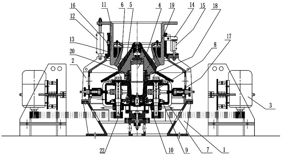
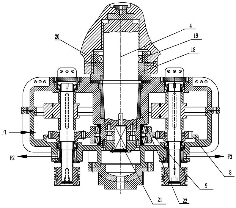

Image

  • Forced synchronous resonance inertia cone crusher
  • Forced synchronous resonance inertia cone crusher
  • Forced synchronous resonance inertia cone crusher

Examples


Embodiment Construction

[0032] The present invention will be described in more detail below in conjunction with the accompanying drawings, so as to facilitate the understanding of those skilled in the art.

[0033] Those skilled in the art should understand that this embodiment is only used to explain the technical principle of the present application, and is not used to limit the protection scope of the present application. Although the components in the accompanying drawings are drawn according to a certain proportional relationship, this proportional relationship is not static, and those skilled in the art can make adjustments to it as needed, so as to adapt to specific applications. The adjusted technical solution is still Will fall into the scope of protection of this application.

[0034] It should also be noted that, in the description of this application, unless otherwise clearly stipulated and limited, the terms "installation", "connection" and "connection" should be understood in a broad se...


PUM


Abstract

The invention discloses a forced synchronous resonance inertia cone crusher which comprises a machine shell, a motor, a vibration exciter, a main vertical shaft, an inner crushing cone and an outer crushing cone which are installed on a machine base, the motor drives the vibration exciter through a transmission assembly, and centrifugal resultant force generated by the vibration exciter drives the main vertical shaft and the inner crushing cone to move synchronously; the vibration exciter comprises a vibration excitation box and a centrifugal mechanism arranged in the vibration excitation box in a sealed mode, the centrifugal mechanism comprises a plurality of sets of centrifugal assemblies arranged outside the main vertical shaft in a balanced mode, all the centrifugal assemblies are driven by a transmission gear set to work, and centrifugal resultant force of all the centrifugal assemblies is transmitted through the vibration excitation box to drive the main vertical shaft to drive the inner crushing cone to rotate and swing; and a self-adjusting discharge mechanism is arranged between the outer crushing cone and the inner crushing cone. The whole forced synchronous resonance inertia cone crusher is simple in structure. The manufacturing process is simple, the manufacturing cost is low, and installation and maintenance are convenient; and compared with a traditional crusher, the vibration crushing efficiency is high, energy consumption is low, and adjustment of the gap of a crushing cavity under the normal working condition can be achieved.

Description

technical field [0001] The invention relates to a cone crusher, in particular to a forced synchronous resonance inertia cone crusher. Background technique [0002] Crusher is suitable for crushing raw materials in metallurgy, construction, road construction, chemical and silicate industries. According to different crushed raw materials, product particle size and output, it is divided into various models. [0003] Vibrating crushers are commonly used equipment in the crushing process. The common ones are vibrating jaw crushers, inertial cone crushers, and self-synchronizing vibrating cone crushers. [0004] The self-synchronizing vibrating cone crusher is a new type of cone crusher successfully developed in recent years. Its structure is as follows: figure 1 As shown, it mainly includes motor 101, elastic coupling 102, vibrator 103, upper connecting plate 104, lower connecting plate 105, guard plate 106, vibration isolation spring 107, bottom plate 108, inner crushing cone 1...

Claims


Application Information

Patent Timeline
IPC IPC(8): B02C2/10B02C23/00B02C23/02
CPCB02C2/10B02C23/00B02C23/02
Inventor 肖为民
Owner 肖为民
Learn More