Spray nozzle and method for atmospheric spraying, device for coating, and coated component

A nozzle and coating technology, applied in the field of components, can solve the problems of high cost, lack of flexibility of the adhesion-enhancing layer, and vacuum method consumption.

Inactive Publication Date: 2012-10-10
SIEMENS AG
View PDF16 Cites 4 Cited by
  • Summary
  • Abstract
  • Description
  • Claims
  • Application Information

AI Technical Summary

Problems solved by technology

At present, HVS is mostly applied in the vacuum method of spraying technology, which is very intensive and expensive
Furthermore, there is a lack of flexibility to use other cladding materials as MCrAlY for the adhesion-promoting layer

Method used


Image

  • Spray nozzle and method for atmospheric spraying, device for coating, and coated component
  • Spray nozzle and method for atmospheric spraying, device for coating, and coated component
  • Spray nozzle and method for atmospheric spraying, device for coating, and coated component

Examples


Embodiment Construction

[0014] The description and drawings illustrate only embodiments of the invention.

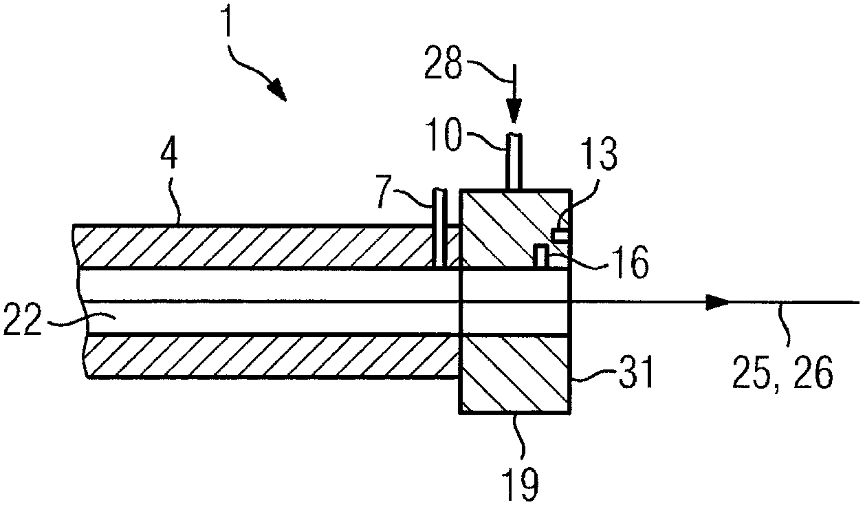
[0015] exist figure 1 The spray head 1 is shown in . The spray head 1 has conventional nozzles 4 and attachments 19 known from the prior art regarding plasma shower heads (APS, . . . ). Parallel to the longitudinal direction 26 of the inner channel 22 of the nozzle 4 , the at least partially melted coating material heated by the plasma flows from the nozzle 4 in an outflow direction 25 . The plasma is generated in the inner channel 22 of the nozzle 4 .

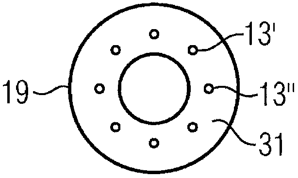
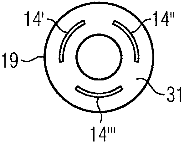
[0016] The nozzle 4 is only modified in that the attachment 19 can be fixed on the nozzle. Attachment 19 extends the inner channel of nozzle 4 . The shielding gas 28 passes through holes 13, 13 ', 13 " (see also figure 2 , 3 ) flows out, and the desired geometry of the shielding gas shield is created around the outflowing cladding material. Shielding gas 28 also can flow out from slit 14 ', 14 ", and described slit is arranged in circle...


PUM


Abstract

By means of a plasma spray nozzle that enables atmospheric plasma spraying using protective gas, it is also possible to deposit oxidation-sensitive metal coatings in atmosphere.

Description

technical field [0001] The invention relates to an atmospheric plasma spraying, a device for coating and a component. Background technique [0002] Atmospheric plasma spraying is a cost-effective alternative to plasma spraying, since a vacuum can be dispensed with here. However, this is not possible with powders. With other coating methods, defined properties of the metal layer are often not achieved. [0003] In order to increase the efficiency of the turbine, the turbine inlet temperature of the gas must be increased. In order to protect the turbine blades from damage at high temperatures of more than 800° C., a metal coating is applied as an oxidation protection and adhesion-promoting layer (HVS), and a ceramic coating is applied on top of this metal coating for thermal insulation. In order to hold the ceramic coating on the adhesion-promoting layer, a particularly rough surface is required. Currently, HVS is mostly applied in the vacuum method of spraying technology,...

Claims


Application Information

Patent Timeline
Patent Type & Authority Applications(China)
IPC IPC(8): B05B1/14B05B7/20B05B15/04C23C4/12H05H1/34B05B1/04B05B12/18
CPCC23C4/127B05B7/08B05B1/046H05H1/34B05B7/205B05B15/0431H05H1/3405H05H1/42Y02T50/67B05B7/20C23C4/134B05B12/18Y02T50/60
Inventor 安迪·博尔夏特马里奥·费尔克尔萨沙·马丁·基耶克马丁·斯坦贝克
Owner SIEMENS AG
Why Eureka
Try Eureka