
Light-emitting device and manufacturing method thereof

一种发光装置、致发光的技术,应用在照明装置、电致发光光源、半导体/固态器件制造等方向,能够解决不能放出、热传导不良等问题,达到放热特性高的效果

Inactive Publication Date: 2012-10-10
SUMITOMO CHEM CO LTD
View PDF7 Cites 5 Cited by
  • Summary
  • Abstract
  • Description
  • Claims
  • Application Information

AI Technical Summary

Problems solved by technology

When the gap is filled with a predetermined gas or is vacuumed, there is a problem that the heat generated in the organic EL element cannot be efficiently released from the sealing substrate due to poor heat conduction from the organic EL element to the sealing substrate.

Method used


Image

  • Light-emitting device and manufacturing method thereof
  • Light-emitting device and manufacturing method thereof
  • Light-emitting device and manufacturing method thereof

Examples


Embodiment Construction

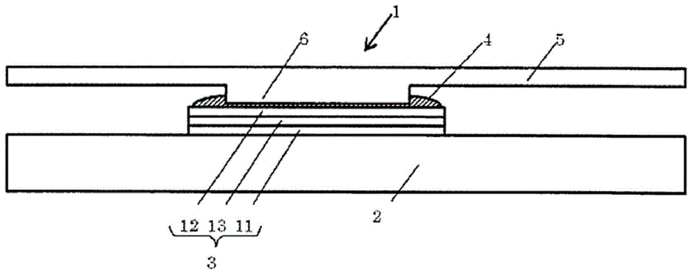
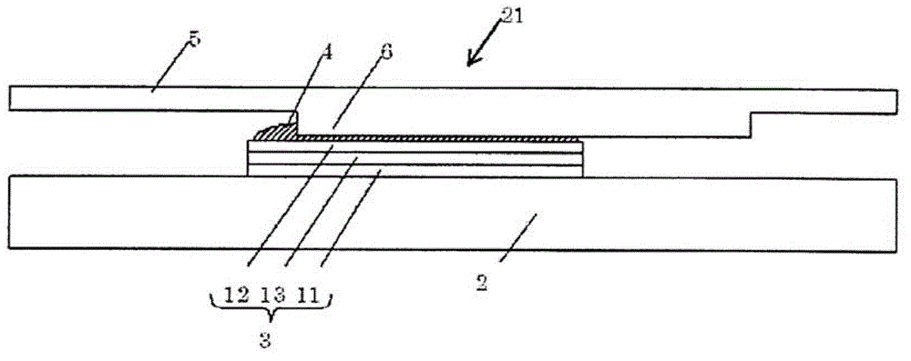
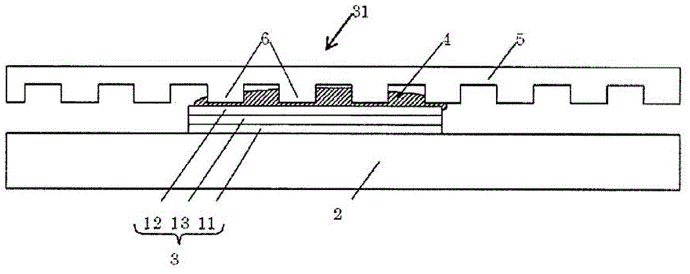
[0048] The light-emitting device of the present invention is sequentially arranged with a supporting substrate, an organic EL element provided on the supporting substrate, a thermally conductive member arranged on the organic EL element, and a sealing substrate for sealing the organic EL element. In the light-emitting device, the The sealing substrate has a convex portion protruding toward the organic EL element, and the convex portion is attached to the organic EL element with the thermally conductive member interposed therebetween. Viewed from one side in the thickness direction of the supporting substrate, the The convex portion is arranged so that part or all thereof overlaps the organic EL element, and an area where the convex portion overlaps the organic EL element is smaller than an area of ​​the organic EL element.

[0049]

[0050] First, the configuration of the light emitting device will be described. figure 1 It is a figure which schematically shows the light-emi...


PUM


Abstract

Disclosed is a light-emitting device that has a structure wherein the film thickness of a heat conductive member can be made thinner. The light-emitting device is provided with a supporting substrate; an organic electroluminescence element arranged on the supporting substrate; a sealing substrate for sealing the organic electroluminescence element, and which has a protrusion section protruding towards the organic electroluminescence element; and the heat conductive member that is formed between the organic electroluminescence element and the protrusion section. The organic electroluminescence element and the protrusion section are adhered together with the heat conductive member intervened therebetween, and a portion or all of the protrusion section is superimposed onto the organic electroluminescence element, when viewed from one direction in the thickness direction of the supporting substrate, and the area wherein the protrusion section is superimposed onto the organic electroluminescence element is smaller than the area of the organic electroluminescence element.

Description

technical field [0001] The invention relates to a light emitting device and a manufacturing method thereof. Background technique [0002] An organic electroluminescent element (hereinafter, sometimes referred to as an "organic EL element") is a light-emitting element that emits light by applying a voltage. Currently, light-emitting devices such as lighting devices and display devices that use the organic EL element as a light source are being paid. Various practicalities. [0003] The organic EL element generates heat during use, and its temperature rises. The increase in temperature of the organic EL element during use increases the deterioration of the element, and therefore various characteristics of the element deteriorate. For example, the brightness half-life becomes shorter. For this reason, various measures against heat generation for reducing the temperature during use have been studied. [0004] An organic EL element is usually provided on a support substrate, ...

Claims


Application Information

Patent Timeline
Patent Type & Authority Applications(China)
IPC IPC(8): H05B33/04H01L51/50H05B33/10
CPCH05B33/10H01L51/529H01L51/524H05B33/04H10K59/8794H10K59/871H10K50/841H10K50/87
Inventor 美马祥司
Owner SUMITOMO CHEM CO LTD
Learn More