Apparatus and method for spray coating

A technology of spraying device and supply device, which is applied in the direction of spraying device, liquid spraying device, and device for coating liquid on the surface. Effect

Active Publication Date: 2017-08-29
SHIMADA APPLI
View PDF7 Cites 1 Cited by
  • Summary
  • Abstract
  • Description
  • Claims
  • Application Information

AI Technical Summary

Problems solved by technology

In addition, the discharge hole at the tip of the nozzle is prone to clogging

Method used


Image

  • Apparatus and method for spray coating
  • Apparatus and method for spray coating
  • Apparatus and method for spray coating

Examples


Embodiment Construction

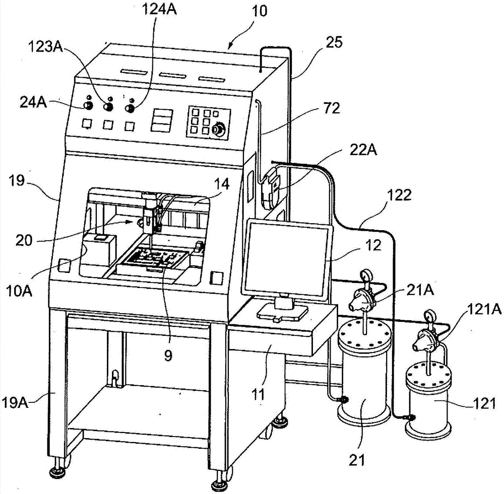
[0041] figure 1 It is a figure which shows the outline|summary of the whole structure of a spraying system.

[0042] The casing 19 of the spraying system 10 is provided on a machine table 19A, and has a working port 10A at the front. The object 9 to be painted is placed in the casing 19 . A coating valve device 20 (spray gun (device)) is disposed above the object 9, and the coating valve device 20 is supported by the robot device 14 and is movable in three-dimensional directions of X, Y, and Z directions. A control panel, display lamps, compressed air pressure regulators 24A and 124 for operation, a compressed air pressure regulator 123A for atomization, etc. are arranged on the upper front surface of the casing 19 . A control device (computer, system) 11 and a CRT display device 12 are provided at a middle height position on the side surface of the casing 19 . A pressure feed tank (liquid coating material storage tank) 21 for a coating liquid and a pressure feed tank (solv...


PUM


Abstract

The present invention relates to a spray coating apparatus and method by which a so-called drawing phenomenon does not occur even if a liquid coating material having high viscosity, such as stock solution, is used. The spray coating apparatus includes a spray gun (coating valve device) (20) having a discharge port for discharging the liquid coating material and an compressed air outlet for pelletizing the liquid coating material discharged from the discharge port; a liquid coating material supply device (21) for supplying a liquid coating material to the spray gun; and a compressed air supply device (120, 220) mixed with solvent mist and generating compressed air mixed with the solvent mist supplied to the compressed air outlet of the spray gun.

Description

technical field [0001] The present invention relates to atomizing liquid materials such as liquid photoresist, moisture-proof insulating agent, surface protection film, and functional coating agent to be coated on semiconductor silicon chips, glass substrates, various mounting substrates, and metal components. The spray coating device and method for forming a thin film on the surface particularly relate to a spray coating device and method capable of preventing the so-called stringing phenomenon from occurring even when a high-viscosity liquid material is used. Background technique [0002] Techniques for partially coating various functional liquid coating agents, moisture-proof insulating materials, etc. on semiconductor silicon, glass substrates, and mounted circuit boards are required. [0003] In addition, in recent high-density mounted small-sized circuit boards, it is also required to partially apply heat dissipation and heat-conducting materials, conductive adhesives,...

Claims


Application Information

Patent Timeline
IPC IPC(8): B05B7/10B05B7/24
CPCB05B7/10B05B7/2489B05B7/0433B05B7/1481B05D1/12
Inventor 岛田隆治岛田千浩
Owner SHIMADA APPLI
Why Eureka
Try Eureka