
Sensor

A technology of sensors and organisms, applied in the field of sensors, can solve the problems of troublesome work, increasing the burden on the examinee, and taking out the needles out of the body together.

Inactive Publication Date: 2012-10-17
TERUMO KK
View PDF1 Cites 0 Cited by
  • Summary
  • Abstract
  • Description
  • Claims
  • Application Information

AI Technical Summary

Problems solved by technology

[0003] However, after the aforementioned sensor is indwelled in the living body via the insertion needle, when the insertion needle is pulled out of the living body, the sensor may be taken out of the living body together with the insertion needle.
Therefore, there is a problem that the sensor has to be reinserted into the living body, or a new sensor has to be used, which makes the operation troublesome and also increases the burden on the examinee.

Method used


Image

  • Sensor
  • Sensor
  • Sensor

Examples


Embodiment Construction

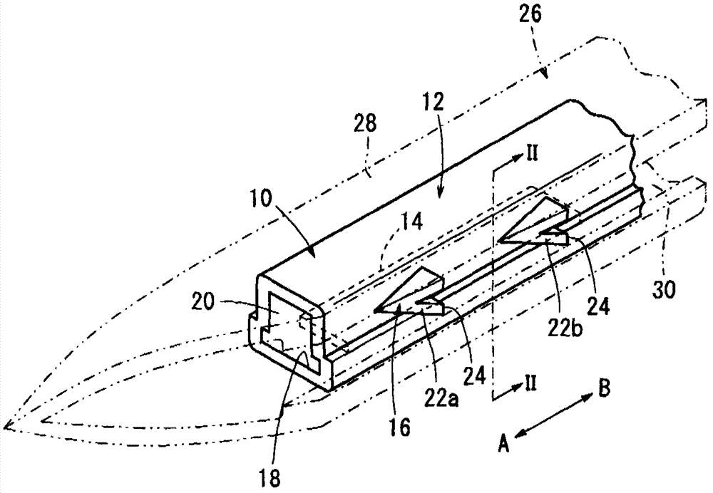
[0021] exist figure 1 In , reference numeral 10 denotes an embedded sensor according to the first embodiment of the present invention.

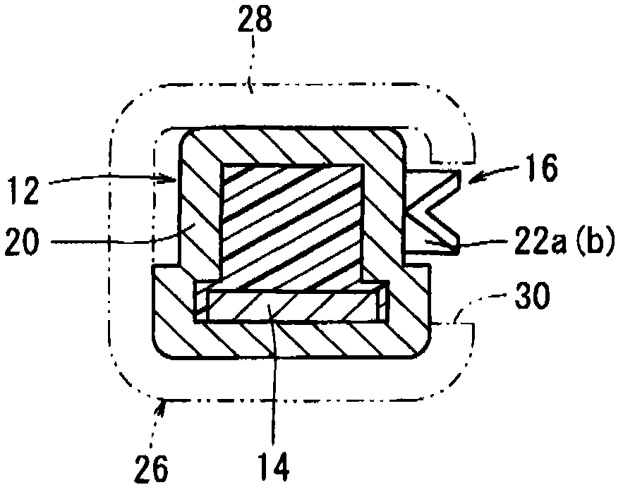
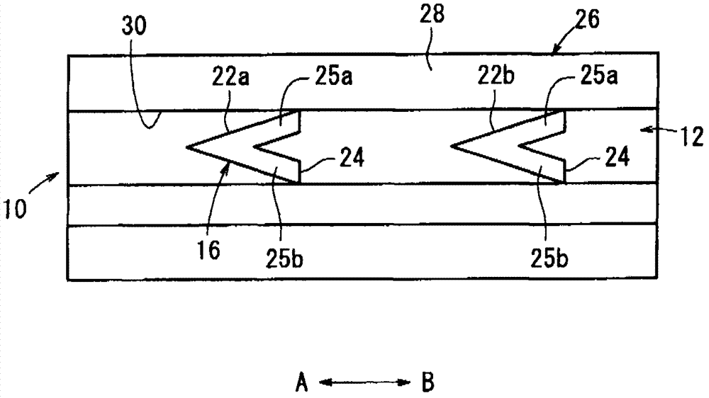
[0022] like Figure 1 to Figure 5 As shown, the embedded sensor 10 includes: a cylindrical sensor body 12; a detection unit 14 housed inside the sensor body 12; an electrical equipment unit 15 for data processing, signal transmission, etc.; Anti-extraction mechanism 16 on the side of 12.

[0023] In addition, in figure 1 In the process, the left side of the sensor main body 12, that is, the embedded sensor 10 is placed toward the living body S (refer to Figure 5 ) at the time of insertion (arrow A direction) is referred to as the “tip end” side, and the right side of the sensor body 12 (arrow B direction) is referred to as the “proximal end” side, and the same applies to other figures.

[0024] The sensor main body 12 is formed in a substantially rectangular cross-section, and has an accommodating portion 18 penetrating therein along the...


PUM


Abstract

An embeddable sensor (10) includes a sensor body (12), a detector (14) housed in the sensor body (12), and a retaining mechanism (16) mounted on a side surface of the sensor body (12). The retaining mechanism (16) includes at least one projection (22a, 22b) on the side surface of the sensor body (12). The projection (22a, 22b) is of a V shape which is progressively wider and higher from a distal end toward a proximal end of the sensor body (12). The projection (22a, 22b) is made of a material whose hardness is lowered upon elapse of a certain period of time within a living body (S). When the embeddable sensor (10) is inserted in the living body (S), the projection (22a, 22b) retains the embeddable sensor (10) within the living body (S). Upon elapse of the certain period of time within the living body (S), the projection (22a, 22b) loses its capability to retain the embeddable sensor (10) within the living body (S).

Description

technical field [0001] The present invention relates to a sensor embedded in a living body to detect an analyte. Background technique [0002] Conventionally, a sensor is placed or embedded in the body of the subject (user), and the analyte in the blood or body fluid of the subject, such as the blood sugar level in the blood, is tested by the sensor. For example, as disclosed in Japanese Patent No. 4065575, the sensor is loaded on an insertion device having an insertion needle for piercing the skin, and the insertion device loaded with the sensor is punctured for the subject, and the above-mentioned The sensor is placed or embedded at a desired position in the living body, and only the insertion core is pulled out of the living body to leave the sensor at the desired position. [0003] However, after the aforementioned sensor is indwelled in the living body via the insertion needle, when the insertion needle is pulled out of the living body, the sensor may be taken out of t...

Claims


Application Information

Patent Timeline
Patent Type & Authority Applications(China)
IPC IPC(8): A61B5/145
CPCA61B5/14532A61B5/14539A61B5/6839A61B2560/063A61B5/14546A61B5/14503
Inventor 陈嵩松本淳时本贵平
Owner TERUMO KK
Learn More